PROCEDURE
- Click here
INSTALL PARK/NEUTRAL POSITION SWITCH ASSEMBLY
-
Temporarily install the park/neutral position switch assembly to the automatic transaxle case sub-assembly with the 2 bolts.
Note:Before installing the park/neutral position switch assembly, remove any dirt or rust on the manual valve lever shaft sub-assembly. Be sure to install the park/neutral position switch assembly straight along the manual valve lever shaft sub-assembly while being careful not to deform the plate spring that supports the manual valve lever shaft sub-assembly. If the plate spring is deformed, the park/neutral position switch assembly cannot be installed correctly.
-
Temporarily install the transmission control shaft lever to the park/neutral position switch assembly.
-
*a P *b N Turn the transmission control shaft lever clockwise until it stops, then turn it counterclockwise 2 notches.
-
Remove the transmission control shaft lever from the park/neutral position switch assembly.
-
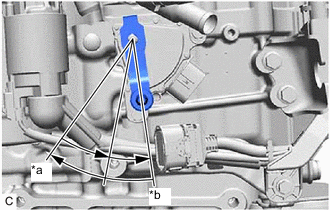
*a Neutral Basic Line *b Protrusion Align the protrusion with the neutral basic line.
-
Hold the park/neutral position switch assembly in that position and tighten the 2 bolts.
5.4 N*m 55 kgf*cm 48 in.*lbf -
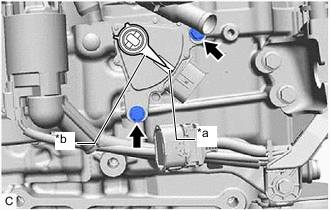
Install the transmission control shaft lever to the manual valve lever shaft sub-assembly with the washer and nut.
12.7 N*m 130 kgf*cm 9 ft.*lbf -
Connect the park/neutral position switch assembly connector.
-
- Click here
CONNECT TRANSMISSION CONTROL CABLE ASSEMBLY
-
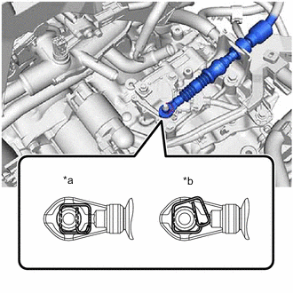
*a Correct *b Incorrect Connect the transmission control cable assembly to the transmission control shaft lever as shown in the illustration.
Note:Before connecting the transmission control cable assembly, check that the park/neutral position switch assembly and shift lever are in N.
-
- Click here
INSTALL BATTERY CLAMP SUB-ASSEMBLY
- Click here
INSTALL ECM
- Click here
INSTALL BATTERY
- Click here
INSPECT PARK/NEUTRAL POSITION SWITCH ASSEMBLY OPERATION
- Click here
INSPECT SHIFT LEVER POSITION
- Click here
ADJUST SHIFT LEVER POSITION