LANE DEPARTURE ALERT SYSTEM(w/ Steering Control) Steering Pad Switch Circuit
DESCRIPTION
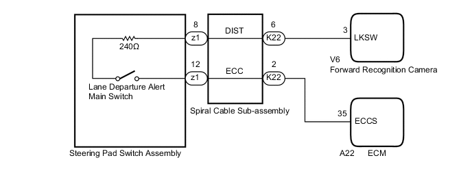
The forward recognition camera receives a lane departure alert main switch signal from the steering pad switch assembly.
WIRING DIAGRAM
Figure 1. for A25A-FKS:

Figure 2. for 2AR-FE:
CAUTION / NOTICE / HINT
Note
The vehicle is equipped with a Supplemental Restraint System (SRS) which includes components such as airbags. Before servicing (including removal or installation of parts), be sure to read the precaution for Supplemental Restraint System.
PROCEDURE
-
INSPECT STEERING PAD SWITCH ASSEMBLY
-
Remove the steering pad switch assembly.
-
Inspect the steering pad switch assembly.
Result Proceed to OK NG
NG 
REPLACE STEERING PAD SWITCH ASSEMBLY Click here
OK 
-
-
INSPECT SPIRAL CABLE SUB-ASSEMBLY
-
Remove the spiral cable sub-assembly.
-
Inspect the spiral cable sub-assembly.
Result Proceed to OK NG
NG
REPLACE SPIRAL CABLE SUB-ASSEMBLY Click here
OK
-
-
CHECK HARNESS AND CONNECTOR (SPIRAL CABLE SUB-ASSEMBLY - FORWARD RECOGNITION CAMERA)
-
Disconnect the K22 spiral cable sub-assembly connector.
-
Disconnect the V6 forward recognition camera connector.
-
Measure the resistance according to the value(s) in the table below.
Standard Resistance Tester Connection Condition Specified Condition K22-6 (DIST) - V6-3 (LKSW) Always Below 1 Ω K22-6 (DIST) or V6-3 (LKSW) - Body ground Always 10 kΩ or higher -
Connect the V6 forward recognition camera connector.
-
Connect the K22 spiral cable sub-assembly connector.
Result Proceed to OK NG
NG
REPAIR OR REPLACE HARNESS OR CONNECTOR
OK
-
-
CHECK HARNESS AND CONNECTOR (SPIRAL CABLE SUB-ASSEMBLY - ECM)
-
for A25A-FKS:
-
Disconnect the K22 spiral cable sub-assembly connector.
-
Disconnect the A24 ECM connector.
-
Measure the resistance according to the value(s) in the table below.
Standard Resistance Tester Connection Condition Specified Condition K22-2 (ECC) - A24-28 (ECCS) Always Below 1 Ω K22-2 (ECC) or A24-28 (ECCS) - Body ground Always 10 kΩ or higher -
Connect the A24 ECM connector.
-
Connect the K22 spiral cable sub-assembly connector.
-
-
for 2AR-FE:
-
Disconnect the K22 spiral cable sub-assembly connector.
-
Disconnect the A22 ECM connector.
-
Measure the resistance according to the value(s) in the table below.
Standard Resistance Tester Connection Condition Specified Condition K22-2 (ECC) - A22-35 (ECCS) Always Below 1 Ω K22-2 (ECC) or A22-35 (ECCS) - Body ground Always 10 kΩ or higher -
Connect the A22 ECM connector.
-
Connect the K22 spiral cable sub-assembly connector.
Result Proceed to OK NG -
OK
PROCEED TO NEXT SUSPECTED AREA SHOWN IN PROBLEM SYMPTOMS TABLE Click here
NG
REPAIR OR REPLACE HARNESS OR CONNECTOR
-