DYNAMIC RADAR CRUISE CONTROL SYSTEM(except 2AR-FE) PRECAUTION
-
PRECAUTION FOR DISCONNECTING CABLE FROM NEGATIVE BATTERY TERMINAL
Note
When disconnecting the cable from the negative (-) battery terminal, initialize the following system(s) after the cable is reconnected:
System See Procedure Lane departure alert system (w/ Steering Control) Pre-collision system Parking assist monitor system -
IGNITION SWITCH EXPRESSIONS
-
The type of ignition switch used on this model differs depending on the specifications of the vehicle. The expressions listed in the table below are used in this section.
Expression Ignition Switch (Position) Engine Switch (Condition) Ignition Switch off LOCK Off (Lock) Ignition Switch ACC ACC On (ACC) Ignition Switch ON ON On (IG) Engine start START On (Start)
-
-
CONSTRUCTION
-
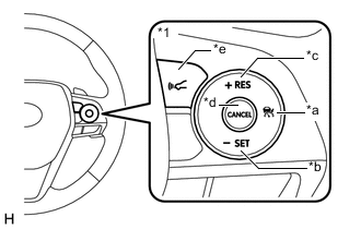
*1 Steering Pad Switch Assembly *a Cruise Control Main Switch *b -SET Switch *c +RES Switch *d CANCEL Switch *e Vehicle-to-vehicle Distance Control Switch The cruise control switch is located on the right side of the steering pad switch assembly.
-
-
HANDLING PRECAUTION FOR DYNAMIC RADAR CRUISE CONTROL SYSTEM
Keep in mind the following points when servicing vehicles equipped with the dynamic radar cruise control system.
-
The dynamic radar cruise control system is designed to be used when driving on highways and freeways. The system may not operate correctly when driving on roads used by pedestrians and bicycles, and may result in an accident.
-
Do not overly rely on the dynamic radar cruise control system.
-
The dynamic radar cruise control system is designed to assist in maintaining an appropriate distance with the preceding vehicle, however, the system alone is not sufficient. Pay constant attention to the vehicle-to-vehicle distance and the traffic conditions when using the dynamic radar cruise control system and decelerate with the brake pedal or accelerate with the accelerator pedal according to the situation to keep an appropriate distance with the preceding vehicle.
-
The dynamic radar cruise control system applies brakes as necessary, however, there is a limitation on the deceleration control capability. When the preceding vehicle decelerates rapidly or another vehicle moves in front of the vehicle, decelerating in time to avoid a collision may not be possible without additional braking.
-
-
The millimeter wave radar sensor dirt detection function.
-
The millimeter wave radar sensor can automatically detect dirt on the sensor face or the front or back surface of the front emblem, however, dirt may not always be detected.
-
The dirt detection function may not operate if a metal object or plastic sheet with metal coating is attached to the sensor or the front emblem.
-
The dirt detection function may not operate if there is snow or ice on the sensor or the front emblem.
Tech Tips
The preceding conditions may result in the vehicle being unable to maintain an appropriate distance with the preceding vehicle.
-
-
Keep the sensor face and the front and back surfaces of the front emblem clean.
-
The dynamic radar cruise control system does not operate or give a vehicle approach warning for vehicles which are stopped or driving at significantly slower speeds.
Tech Tips
This includes vehicles stopped at a tollgate or in traffic, or a preceding vehicle driving at significantly slower speeds.
-
When following another vehicle with vehicle-to-vehicle distance control mode controlling vehicle speed, the vehicle will not accelerate if the +RES switch is pushed, as the speed is controlled in accordance with the speed of the preceding vehicle.
Note
If the set vehicle speed is increased by pushing the +RES switch, the vehicle will accelerate to the newly set speed when the preceding vehicle moves out of the lane.
Tech Tips
The set vehicle speed can be confirmed on the multi-information display.
-
The actual vehicle-to-vehicle distance may be shorter than the set vehicle-to-vehicle distance when driving on a downhill road.
-
When a system malfunction is detected, the master warning light illuminates, a warning message is displayed on the multi-information display in the combination meter assembly and the buzzer sounds.
-
Keep the windshield glass clean.
-
Do not apply excessive force to the forward recognition camera or subject it to a strong impact.
-
Do not disassemble the forward recognition camera.
-
Do not attach a sticker to the windshield glass in the area in front of the forward recognition camera.
-
If the heater is used with FOOT mode selected, the upper area of the windshield glass may fog up, affecting the operation of the forward recognition camera.
Tech Tips
If the windshield glass fogs up, clear it using the front defroster.
-
Do not damage the forward recognition camera lens or allow it to become dirty.
Tech Tips
-
When cleaning the inner surface of the windshield glass, do not allow cleaning agent to contact the forward recognition camera lens.
-
Do not touch the forward recognition camera lens.
-
-
Do not place any objects on top of the instrument panel.
Tech Tips
If an object is reflecting off of the windshield glass, the performance of the forward recognition camera may decrease.
-
The vehicle approach warning buzzer does not sound when constant speed control mode is controlling vehicle speed.
-
As the controls performed by constant speed control mode and vehicle-to-vehicle distance control mode are different, always confirm which mode is selected before operating the dynamic radar cruise control system.
-
For other precautions related to constant speed control mode, refer to Precautions for the conventional cruise control system.
-
-
HANDLING PRECAUTIONS FOR FORWARD RECOGNITION CAMERA
-
PRECAUTION WHEN REPLACING ECM
Before replacing the ECM, refer to Service Bulletin.
-
PRECAUTIONS WHEN REPLACING MILLIMETER WAVE RADAR SENSOR ASSEMBLY
When the millimeter wave radar sensor assembly is replaced with a new one, adjustment of the radar sensor beam axis must be performed.
-
PRECAUTIONS WHEN REPLACING FORWARD RECOGNITION CAMERA
If the forward recognition camera has been replaced with a new one, be sure to perform Recognition Camera/Target Position Memory and Recognition Camera Axis Adjust.
-
PRECAUTION WHEN REPLACING BRAKE ACTUATOR ASSEMBLY (SKID CONTROL ECU)
After the brake actuator assembly (skid control ECU) is replaced, perform the yaw rate sensor and G sensor zero point calibration and store the system information.