DYNAMIC RADAR CRUISE CONTROL SYSTEM(for 2AR-FE) ECU Power Source Circuit
DESCRIPTION
This circuit supplies power to the millimeter wave radar sensor assembly when the ignition switch is ON.
WIRING DIAGRAM
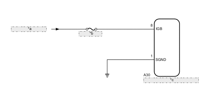
| *a | from IG1-NO. 1 Relay |
| *b | ECU-IG1 NO. 3 |
| *c | Millimeter Wave Radar Sensor Assembly |
CAUTION / NOTICE / HINT
Note
Inspect the fuses for circuits related to this system before performing the following inspection procedure.
PROCEDURE
-
CHECK MILLIMETER WAVE RADAR SENSOR ASSEMBLY (IGB VOLTAGE)
-
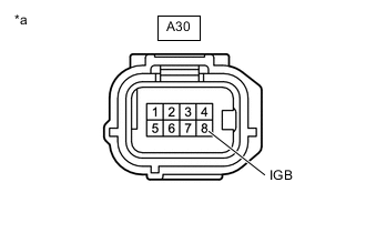
*a Front view of wire harness connector
(to Millimeter Wave Radar Sensor Assembly)
Disconnect the A30 millimeter wave radar sensor assembly connector.
-
Turn the ignition switch to ON.
-
Measure the voltage according to the value(s) in the table below.
Standard Voltage Tester Connection Condition Specified Condition A30-8 (IGB) - Body ground Ignition switch ON 11 to 14 V -
Turn the ignition switch off.
-
Connect the A30 millimeter wave radar sensor assembly connector.
Result Proceed to OK NG
NG 
REPAIR OR REPLACE HARNESS OR CONNECTOR (POWER SOURCE CIRCUIT)
OK 
-
-
CHECK HARNESS AND CONNECTOR (MILLIMETER WAVE RADAR SENSOR ASSEMBLY - BODY GROUND)
-
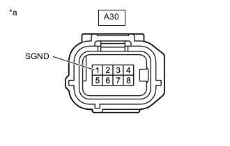
*a Front view of wire harness connector
(to Millimeter Wave Radar Sensor Assembly)
Disconnect the A30 millimeter wave radar sensor assembly connector.
-
Measure the resistance according to the value(s) in the table below.
Standard Resistance Tester Connection Condition Specified Condition A30-1 (SGND) - Body ground Always Below 1 Ω -
Connect the A30 millimeter wave radar sensor assembly connector.
Result Proceed to OK NG
OK
PROCEED TO NEXT SUSPECTED AREA SHOWN IN PROBLEM SYMPTOMS TABLE Click here
NG
REPAIR OR REPLACE HARNESS OR CONNECTOR
-