AUTOMATIC TRANSAXLE UNIT DISASSEMBLY

PROCEDURE
-
REMOVE TRANSMISSION CONTROL SHAFT LEVER
-
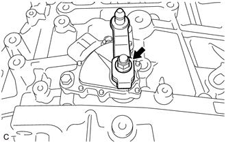
Remove the nut, washer and transmission control shaft lever from the manual valve lever shaft sub-assembly.
-
-
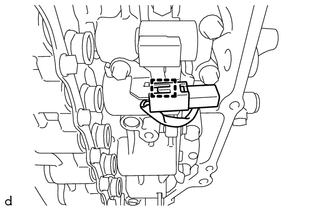
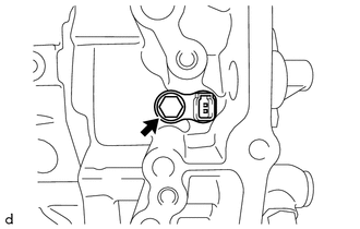
REMOVE PARK/NEUTRAL POSITION SWITCH ASSEMBLY
-
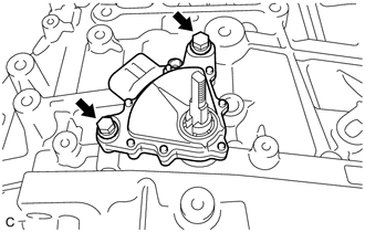
Remove the 2 bolts and park/neutral position switch assembly from the automatic transaxle case sub-assembly.
-
-
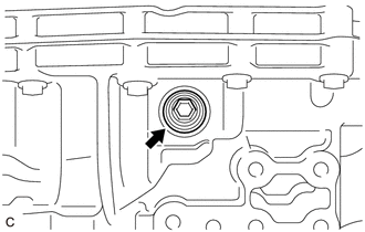
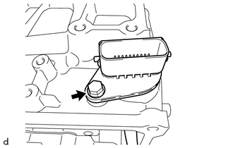
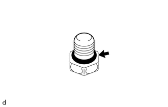
REMOVE REFILL PLUG
-
Remove the refill plug and gasket from the automatic transaxle case sub-assembly.
-
-
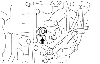
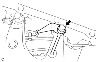
REMOVE OVERFLOW PLUG
-
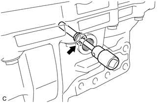
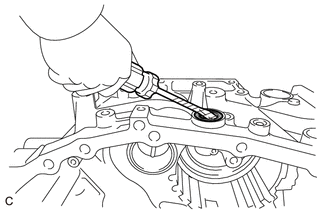
Using a 10 mm socket hexagon wrench, remove the overflow plug and gasket from the transaxle housing.
-
-
REMOVE NO. 1 TRANSMISSION OIL FILLER TUBE
-
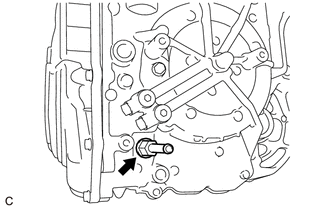
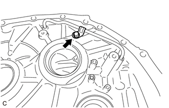
Using a 6 mm socket hexagon wrench, remove the No. 1 transmission oil filler tube from the transaxle housing.
-
-
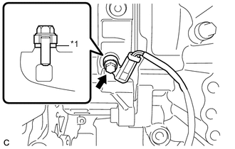
REMOVE OIL COOLER UNION SUB-ASSEMBLY
-
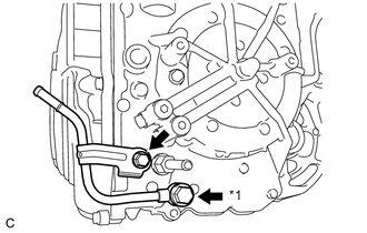
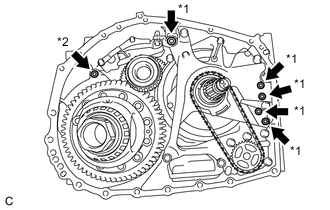
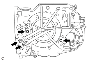
*1 Oil Cooler Union Bolt Remove the bolt to separate the oil cooler union sub-assembly bracket portion from the automatic transaxle case sub-assembly.
-
Remove the oil cooler union bolt, 2 gaskets and oil cooler union sub-assembly from the automatic transaxle case sub-assembly.
-
-
REMOVE NO. 1 OIL COOLER OUTLET TUBE SUB-ASSEMBLY
-
Using a 19 mm union nut wrench, remove the No. 1 oil cooler outlet tube sub-assembly from the automatic transaxle case sub-assembly.
-
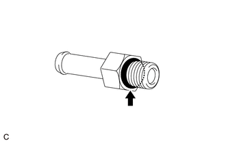
Remove the O-ring from the No. 1 oil cooler outlet tube sub-assembly.
-
-
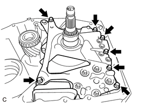
REMOVE TRANSMISSION CASE SIDE COVER
-
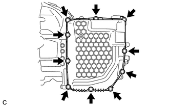
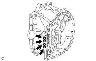
Remove the 10 bolts and transmission case side cover from the automatic transaxle case sub-assembly.
-
-
REMOVE TRANSMISSION WIRE
-
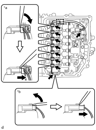
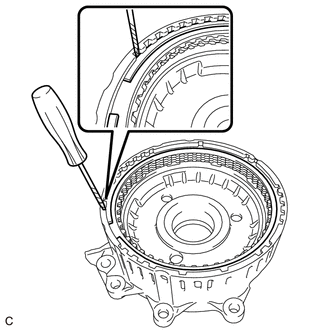
*a Connector (A) *b Connector (B) Disengage the clamp to disconnect the transmission wire from the solenoid lock plate.
-
Disconnect the 9 solenoid valve connectors.
Tech Tips
-
Using a screwdriver, disconnect the solenoid valve connector (A) using the procedure shown in the illustration.
-
Using a screwdriver, disconnect the solenoid valve connector (B) using the procedure shown in the illustration.
-
-
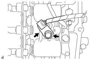
Remove the bolt and temperature sensor clamp and disconnect the temperature sensor from the transmission valve body assembly.
-
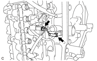
Disconnect the transmission revolution sensor (NT) connector and transmission revolution sensor (NC) connector.
-
Remove the bolt and transmission wire from the automatic transaxle case sub-assembly.
-
-
REMOVE TRANSMISSION VALVE BODY ASSEMBLY
-
Disengage the clamp to disconnect the transmission revolution sensor (NC) wire connector.
-
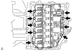
Remove the 9 bolts and transmission valve body assembly from the automatic transaxle case sub-assembly.
-
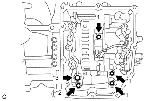
*1 Transaxle Case Gasket *2 No. 1 Front Oil Pump Cover Gasket *3 No. 2 Front Oil Pump Cover Gasket Remove the 2 transaxle case gaskets from the automatic transaxle case sub-assembly.
-
Remove the transaxle case gasket from the counter drive gear sub-assembly.
-
Remove the No. 1 front oil pump cover gasket from the front oil pump assembly.
-
Remove the No. 2 front oil pump cover gasket from the front oil pump assembly.
-
-
REMOVE TRANSMISSION REVOLUTION SENSOR (NT)
-
Remove the bolt and transmission revolution sensor (NT) from the automatic transaxle case sub-assembly.
-
-
REMOVE TRANSMISSION REVOLUTION SENSOR (NC)
-
*1 Spacer Remove the bolt, spacer and transmission revolution sensor (NC) from the counter drive gear sub-assembly.
-
-
INSPECT INPUT SHAFT END PLAY
-
REMOVE TRANSAXLE HOUSING
-
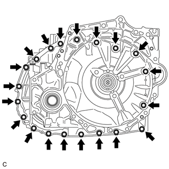
Remove the 20 bolts.
-
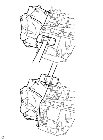
Using a plastic hammer, tap on the circumference of the transaxle housing to remove it from the automatic transaxle case sub-assembly.
-
*1 Transaxle Case Gasket *2 O-ring Remove the 5 transaxle case gaskets from the front oil pump assembly.
-
Remove the O-ring from the automatic transaxle case sub-assembly.
-
-
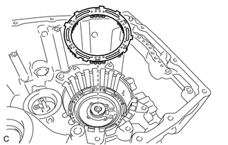
REMOVE TRANSAXLE HOUSING OIL SEPARATOR
-
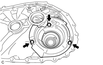
Remove the 3 bolts and transaxle housing oil separator from the transaxle housing.
-
-
REMOVE TRANSMISSION OIL CLEANER MAGNET
-
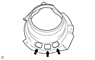
Remove the 3 transmission oil cleaner magnets from the transaxle housing oil separator.
-
-
INSPECT TRANSMISSION OIL CLEANER MAGNET
-
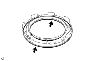
REMOVE DIFFERENTIAL GEAR LUBE APPLY TUBE
-
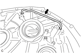
Remove the differential gear lube apply tube from the transaxle housing.
-
-
REMOVE TRANSMISSION LUBE APPLY TUBE
-
Remove the bolt and clamp from the transaxle housing.
-
Remove the transmission lube apply tube from the transaxle housing.
-
-
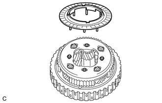
REMOVE DIFFERENTIAL CASE ASSEMBLY
-
Remove the differential case assembly from the automatic transaxle case sub-assembly.
-
-
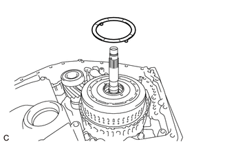
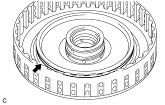
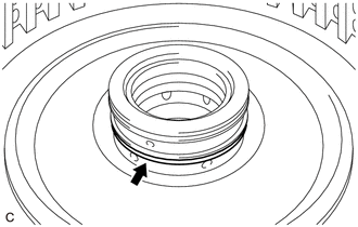
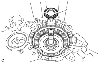
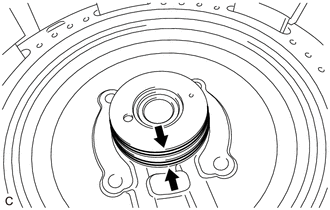
REMOVE CLUTCH DRUM OIL SEAL RING
-
Remove the clutch drum oil seal ring from the front oil pump assembly.
-
-
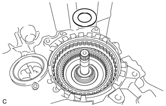
REMOVE OIL PUMP SPROCKET FRONT THRUST WASHER
-
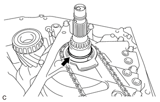
Remove the oil pump sprocket front thrust washer from the transmission oil pump drive sprocket.
-
-
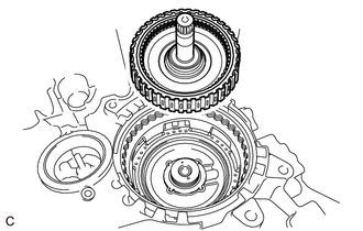
REMOVE TRANSMISSION DRIVE CHAIN
-

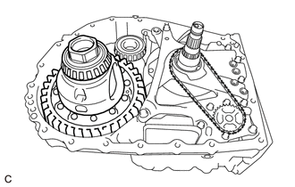
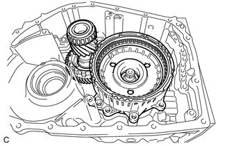
Remove the transmission drive chain together with the transmission oil pump drive sprocket and oil pump drive shaft sub-assembly from the front oil pump assembly.
Note
To avoid damaging the bush of the front oil pump assembly, remove the transmission drive chain, transmission oil pump drive sprocket and oil pump drive shaft sub-assembly horizontally relative to the front oil pump assembly.
-
-
REMOVE OIL PUMP SPROCKET REAR THRUST WASHER
-
Remove the oil pump sprocket rear thrust washer from the front oil pump assembly.
-
-
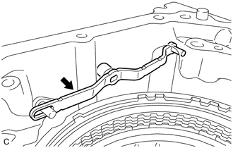
REMOVE MANUAL DETENT SPRING SUB-ASSEMBLY
-
Remove the bolt and manual detent spring sub-assembly from the front oil pump assembly.
-
-
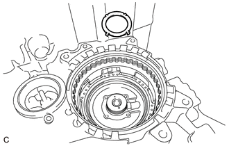
REMOVE FRONT OIL PUMP ASSEMBLY
Note
To avoid damaging the front oil pump assembly and transmission valve body assembly, when removing the front oil pump assembly, first remove the transmission valve body assembly.
-
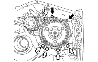
Remove the 7 bolts and front oil pump assembly from the automatic transaxle case sub-assembly.
-
-
REMOVE PLANETARY CARRIER THRUST WASHER
-
Remove the planetary carrier thrust washer from the C-3 and C-4 clutch assembly.
-
-
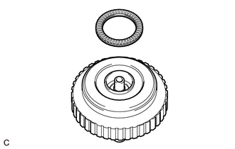
REMOVE C-3 AND C-4 CLUTCH ASSEMBLY
-
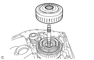
Remove the C-3 and C-4 clutch assembly from the front planetary gear assembly.
-
-
INSPECT CLEARANCE OF C-3 CLUTCH
-
INSPECT CLEARANCE OF C-4 CLUTCH
-
REMOVE NO. 2 PLANETARY CARRIER THRUST WASHER
-
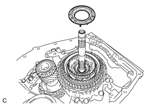
Remove the No. 2 planetary carrier thrust washer from the front planetary gear assembly.
-
-
REMOVE PLANETARY SUN GEAR
-
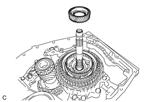
Remove the planetary sun gear from the front planetary gear assembly.
-
-
REMOVE NO. 9 THRUST BEARING RACE
-
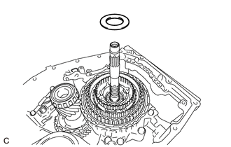
Remove the No. 9 thrust bearing race from the front planetary gear assembly.
-
-
REMOVE THRUST NEEDLE ROLLER BEARING
-
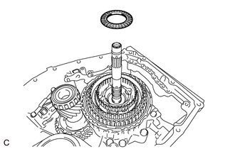
Remove the thrust needle roller bearing from the front planetary gear assembly.
-
-
REMOVE NO. 8 THRUST BEARING RACE
-
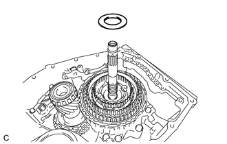
Remove the No. 8 thrust bearing race from the front planetary gear assembly.
-
-
REMOVE FRONT PLANETARY GEAR ASSEMBLY
-
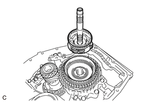
Remove the front planetary gear assembly from the front planetary ring gear.
-
-
REMOVE THRUST NEEDLE ROLLER BEARING
-
Remove the thrust needle roller bearing from the front planetary ring gear.
-
-
REMOVE NO. 7 THRUST BEARING RACE
-
Remove the No. 7 thrust bearing race from the front planetary gear assembly.
-
-
INSPECT FRONT PLANETARY GEAR ASSEMBLY
-
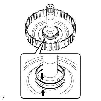
REMOVE INPUT SHAFT OIL SEAL RING
-
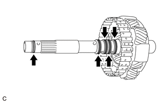
Remove the 5 input shaft oil seal rings from the front planetary gear assembly.
Note
Do not expand the gap of the input shaft oil seal rings excessively.
-
-
REMOVE REAR INPUT SHAFT OIL SEAL RING
-
Remove the 2 rear input shaft oil seal rings from the front planetary gear assembly.
Note
Do not expand the gap of the rear input shaft oil seal rings excessively.
-
-
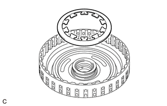
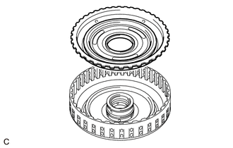
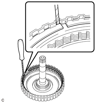
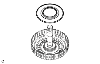
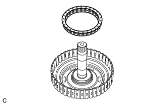
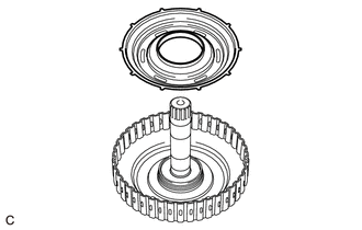
REMOVE FRONT PLANETARY RING GEAR
-
Remove the front planetary ring gear with front planetary ring gear flange from the C-1 clutch assembly.
-
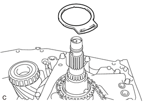
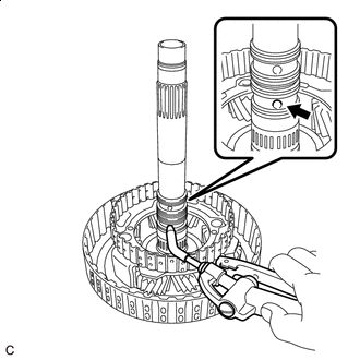
Using a screwdriver with its tip wrapped with protective tape, remove the snap ring from the front planetary ring gear.
Note
Be careful not to damage the front planetary ring gear and front planetary ring gear flange.
-
Remove the front planetary ring gear flange from the front planetary ring gear.
-
-
REMOVE THRUST NEEDLE ROLLER BEARING
-
Remove the thrust needle roller bearing from the C-1 clutch assembly.
-
-
REMOVE NO. 6 THRUST BEARING RACE
-
Remove the No. 6 thrust bearing race from the C-1 clutch assembly.
-
-
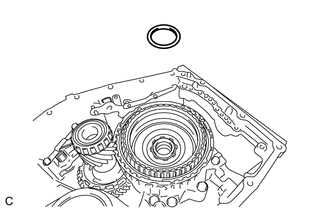
REMOVE C-1 CLUTCH ASSEMBLY
-
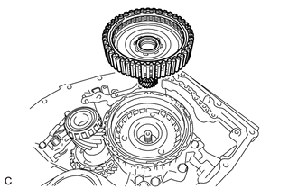
Remove the C-1 clutch assembly from the counter drive gear sub-assembly.
-
-
INSPECT CLEARANCE OF C-1 CLUTCH
-
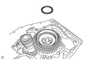
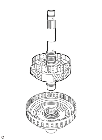
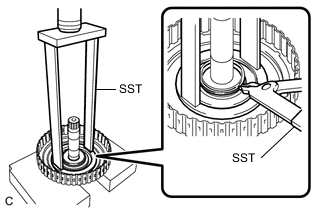
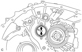
REMOVE REAR PLANETARY SUN GEAR SUB-ASSEMBLY
-
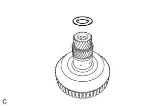
Remove the No. 3 thrust bearing race from the rear planetary sun gear sub-assembly.
-
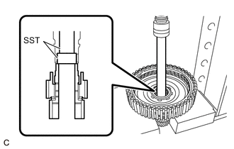
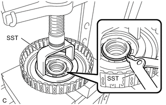
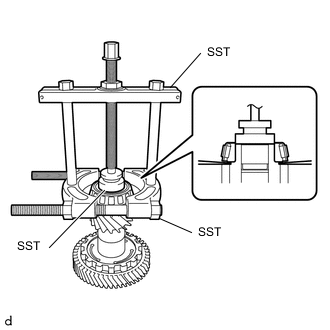
Using SST and a press, remove the rear planetary sun gear sub-assembly from the C-1 clutch assembly.
- SST
- 09950-60010 ( 09951-00260 )
- 09950-70010 ( 09951-07200 )
-
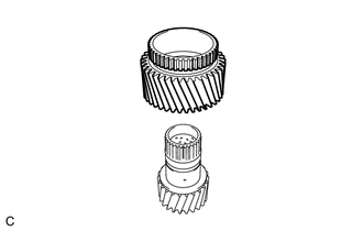
Remove the planetary sun gear sub-assembly from the rear planetary sun gear sub-assembly.
-
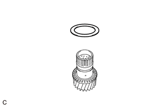
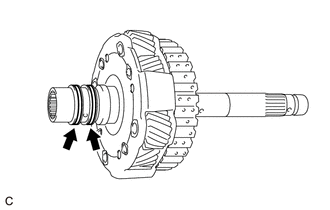
Remove the No. 4 thrust bearing race from the rear planetary sun gear sub-assembly.
-
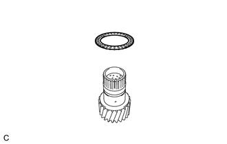
Remove the thrust needle roller bearing from the rear planetary sun gear sub-assembly.
-
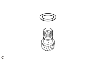
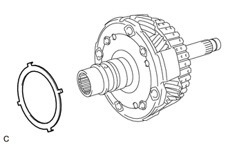
Remove the thrust bearing race from the rear planetary sun gear sub-assembly.
-
-
INSPECT PLANETARY SUN GEAR SUB-ASSEMBLY
-
INSPECT REAR PLANETARY SUN GEAR SUB-ASSEMBLY
-
REMOVE C-1 CLUTCH ASSEMBLY
-
Remove the C-1 clutch assembly from the sun gear input hub sub-assembly.
-
-
REMOVE THRUST NEEDLE ROLLER BEARING
-
Remove the thrust needle roller bearing from the sun gear input hub sub-assembly.
-
-
REMOVE NO. 5 THRUST BEARING RACE
-
Remove the No. 5 thrust bearing race from the sun gear input hub sub-assembly.
-
-
REMOVE TOLERANCE RING
-
Using a screwdriver with its tip wrapped in protective tape, remove the tolerance ring from the clutch drum sub-assembly.
Note
Be careful not to damage the clutch drum sub-assembly.
-
-
REMOVE FRONT CLUTCH CLUTCH DISC
-
Using a screwdriver with its tip wrapped in protective tape, remove the snap ring from the clutch drum sub-assembly.
Note
Be careful not to damage the clutch drum sub-assembly.
-
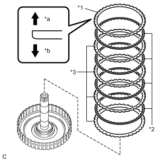
*1 Forward Clutch Flange *2 Front Clutch Clutch Disc *3 Forward Multiple Disc Clutch Clutch Plate *a Snap Ring Side *b Front Clutch Clutch Disc Side Remove the forward clutch flange, 4 front clutch clutch discs and 4 forward multiple disc clutch clutch plates from the clutch drum sub-assembly.
-
-
INSPECT FRONT CLUTCH CLUTCH DISC
-
REMOVE NO. 1 CLUTCH BALANCER
-
Place SST on the No. 1 clutch balancer and compress the rear clutch piston return compression spring with a press.
- SST
- 09320-89010
Note
Do not compress the rear clutch piston return compression spring excessively.
-
Using SST, remove the snap ring from the clutch drum sub-assembly.
- SST
- 09350-30020 ( 09350-07070 )
-
Remove the No. 1 clutch balancer from the forward clutch piston.
-
-
REMOVE REAR CLUTCH PISTON RETURN COMPRESSION SPRING
-
Remove the rear clutch piston return compression spring from the forward clutch piston.
-
-
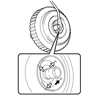
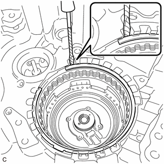
REMOVE FORWARD CLUTCH PISTON
-
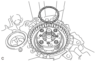
Set the front planetary gear assembly on the clutch drum sub-assembly.
-

Cover Oil Hole Apply compressed air (392 kPa (4.0 kgf/cm2, 57 psi)) to the oil hole of the front planetary gear assembly to separate the forward clutch piston from the clutch drum sub-assembly.
Note
Be careful as ATF may spray when applying compressed air.
Tech Tips
Make sure to cover the ATF hole shown in the illustration.
-
Remove the forward clutch piston from the clutch drum sub-assembly.
-
Remove the O-ring from the clutch drum sub-assembly.
-
Remove the D-ring from the clutch drum sub-assembly.
-
-
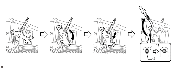
REMOVE MANUAL VALVE LEVER SHAFT SUB-ASSEMBLY
-
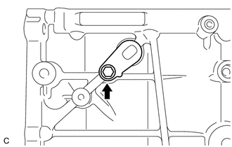
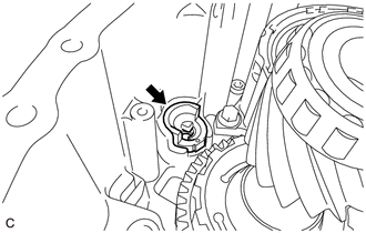
Remove the bolt.
-
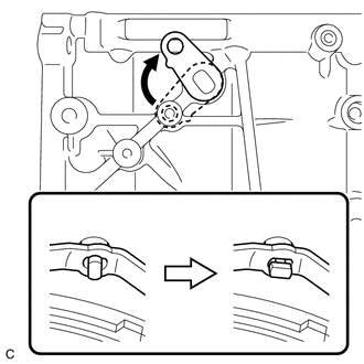
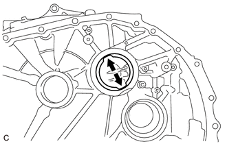
Align the cutouts of the manual valve lever sub-assembly and manual valve lever shaft sub-assembly, and remove the manual valve lever shaft sub-assembly.
Tech Tips
Rotating the manual valve lever shaft sub-assembly to the area shown in the illustration will align the cutouts.
-
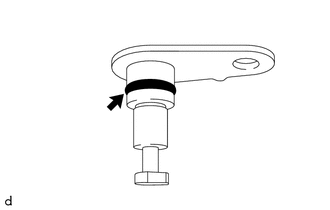
Remove the O-ring from the manual valve lever shaft sub-assembly.
-
-
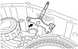
REMOVE MANUAL VALVE LEVER SUB-ASSEMBLY
-
Remove the manual valve lever sub-assembly from the automatic transaxle case sub-assembly.
-
-
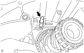
REMOVE PAWL STOPPER PLATE
-
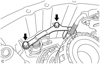
Remove the 2 bolts and pawl stopper plate from the automatic transaxle case sub-assembly.
-
-
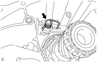
REMOVE MANUAL VALVE LEVER SHAFT RETAINER SPRING
-
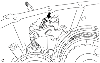
Remove the manual valve lever shaft retainer spring from the automatic transaxle case sub-assembly.
-
-
REMOVE PARKING LOCK ROD SUB-ASSEMBLY
-
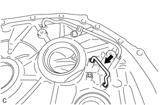
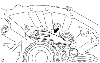
Move the manual valve lever shaft sub-assembly and parking lock rod sub-assembly as shown in the illustration, and remove the parking lock rod sub-assembly.
*1 Manual Valve Lever Shaft Sub-assembly *2 Parking Lock Rod Sub-assembly Tech Tips
Align the cutouts of the parking lock rod sub-assembly and manual valve lever shaft sub-assembly and remove the parking lock rod sub-assembly.
-
-
REMOVE MANUAL VALVE LEVER SHAFT SUB-ASSEMBLY
-
Remove the manual valve lever shaft sub-assembly from the automatic transaxle case sub-assembly.
-
-
REMOVE PARKING LOCK PAWL TORSION SPRING
-
Remove the parking lock pawl torsion spring from the automatic transaxle case sub-assembly.
-
-
REMOVE PARKING LOCK PAWL SHAFT
-
Remove the parking lock pawl shaft from the automatic transaxle case sub-assembly.
-
-
REMOVE PARKING LOCK PAWL
-
Remove the parking lock pawl from the automatic transaxle case sub-assembly.
-
-
REMOVE PARKING LOCK SLEEVE
-
Remove the parking lock sleeve from the automatic transaxle case sub-assembly.
-
-
INSPECT CLEARANCE OF B-1 BRAKE
-
REMOVE COUNTER DRIVE GEAR SUB-ASSEMBLY
-
"TORX" Bolt 
Bolt Using a T50 "TORX" socket wrench, remove the 2 "TORX" bolts from the counter drive gear sub-assembly.
-
Remove the 5 bolts from the counter drive gear sub-assembly.
-
Remove the counter drive gear sub-assembly together with the pinion and counter driven gear sub-assembly from the automatic transaxle case sub-assembly.
-

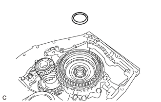
Remove the O-ring from the automatic transaxle case sub-assembly.
-
-
REMOVE NO. 1 BRAKE DISC
-
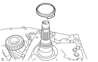
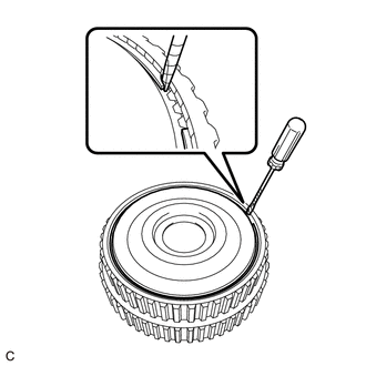
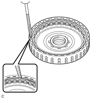
Using a screwdriver with its tip wrapped in protective tape, remove the snap ring from the counter drive gear sub-assembly.
Note
Be careful not to damage the counter drive gear sub-assembly.
-
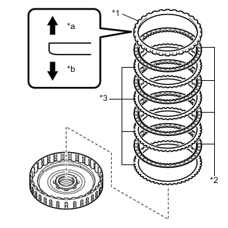
*1 No. 1 Brake Flange *2 No. 1 Brake Disc *3 No. 1 Brake Plate *a Snap Ring Side *b No. 1 Brake Disc Side Remove the No. 1 brake flange, 4 No. 1 brake discs and 4 No. 1 brake plates from the counter drive gear sub-assembly.
-
-
INSPECT NO. 1 BRAKE DISC
-
REMOVE NO. 3 PLANETARY CARRIER THRUST WASHER
-
Remove the No. 3 planetary carrier thrust washer from the rear planetary gear assembly.
-
-
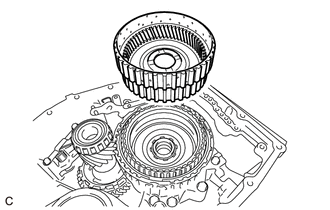
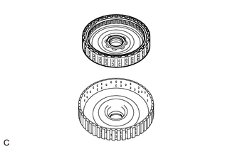
REMOVE REAR PLANETARY GEAR ASSEMBLY
-
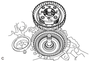
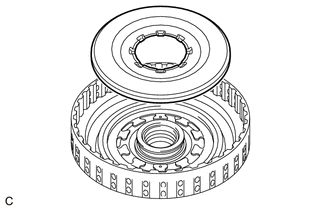
Remove the rear planetary gear assembly from the C-2 clutch assembly.
-
-
REMOVE NO. 4 PLANETARY CARRIER THRUST WASHER
-
Remove the No. 4 planetary carrier thrust washer from the rear planetary gear assembly.
-
-
INSPECT REAR PLANETARY GEAR ASSEMBLY
-
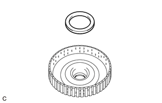
REMOVE THRUST NEEDLE ROLLER BEARING
-
Remove the thrust needle roller bearing from the C-2 clutch assembly.
-
-
REMOVE NO. 2 THRUST BEARING RACE
-
Remove the No. 2 thrust bearing race from the C-2 clutch assembly.
-
-
INSPECT CLEARANCE OF C-2 CLUTCH
-
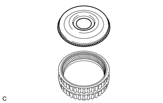
REMOVE C-2 CLUTCH ASSEMBLY
-
Remove the C-2 clutch assembly from the automatic transaxle case sub-assembly.
-
-
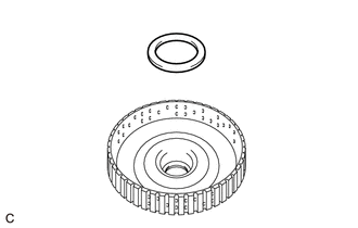
REMOVE THRUST NEEDLE ROLLER BEARING
-
Remove the thrust needle roller bearing from the C-2 clutch assembly.
-
-
REMOVE NO. 1 THRUST BEARING RACE
-
Remove the No. 1 thrust bearing race from the automatic transaxle case sub-assembly.
-
-
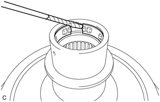
REMOVE NO. 2 CLUTCH DISC
-
Using a screwdriver with its tip wrapped in protective tape, remove the snap ring from the intermediate shaft sub-assembly.
Note
Be careful not to damage the intermediate shaft sub-assembly.
-
*1 Direct Clutch Flange *2 No. 2 Clutch Disc *3 No. 2 Clutch Plate *a Snap Ring Side *b No. 2 Clutch Disc Side Remove the direct clutch flange, 4 No. 2 clutch discs and 4 No. 2 clutch plates from the intermediate shaft sub-assembly.
-
-
INSPECT NO. 2 CLUTCH DISC
-
REMOVE C-2 CLUTCH BALANCER
-
Place SST on the C-2 clutch balancer and compress the clutch return spring sub-assembly with a press.
- SST
- 09387-00020
Note
Do not compress the clutch return spring sub-assembly excessively.
-
Using SST, remove the snap ring from the intermediate shaft sub-assembly.
- SST
- 09350-30020 ( 09350-07070 )
-
Remove the C-2 clutch balancer from the intermediate shaft sub-assembly.
-
-
REMOVE CLUTCH RETURN SPRING SUB-ASSEMBLY
-
Remove the clutch return spring sub-assembly from the intermediate shaft sub-assembly.
-
-
INSPECT CLUTCH RETURN SPRING SUB-ASSEMBLY
-
REMOVE C-2 CLUTCH PISTON
-
Apply Compressed Air Cover Oil Hole Apply compressed air (392 kPa (4.0 kgf/cm2, 57 psi)) to the oil hole of the intermediate shaft sub-assembly.
Note
-
Applying compressed air may cause the C-2 clutch piston to jump out. When removing the C-2 clutch piston, hold it by hand using a piece of cloth.
-
Be careful as ATF may spray when applying compressed air.
Tech Tips
Cover all of the oil holes with tape except the oil hole to which compressed air will be applied.
-
-
Remove the C-2 clutch piston from the intermediate shaft sub-assembly.
-
Remove the 2 O-rings from the intermediate shaft sub-assembly.
-
-
REMOVE DIRECT CLUTCH DRUM OIL SEAL RING
-
Remove the 2 direct clutch drum oil seal rings from the automatic transaxle case sub-assembly.
-
-
INSPECT CLEARANCE OF B-2 BRAKE
-
REMOVE 2ND BRAKE BRAKE DISC
-
Using a screwdriver with its tip wrapped with protective tape, remove the snap ring from the automatic transaxle case sub-assembly.
Note
Be careful not to damage the automatic transaxle case sub-assembly.
-
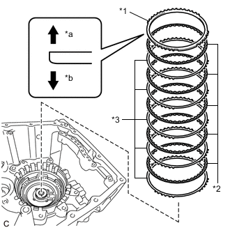
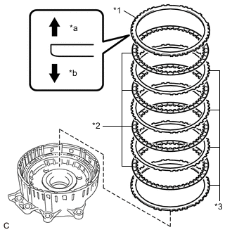
*1 2nd Brake Brake Flange *2 2nd Brake Brake Disc *3 2nd Brake Brake Plate *a Snap Ring Side *b 2nd Brake Brake Disc Side Remove the 2nd brake brake flange, 5 2nd brake brake discs and 5 2nd brake brake plates from the automatic transaxle case sub-assembly.
-
-
INSPECT 2ND BRAKE BRAKE DISC
-
REMOVE NO. 2 1ST AND REVERSE BRAKE PISTON
-
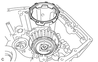
Remove the No. 2 1st and reverse brake piston from the automatic transaxle case sub-assembly.
-
-
REMOVE 1ST AND REVERSE BRAKE RETURN SPRING SUB-ASSEMBLY
-
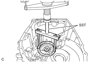
Place SST on the 1st and reverse brake return spring sub-assembly and compress it with a press.
- SST
- 09380-60011 ( 09381-06020, 09381-06050, 09381-06070 )
- 09950-70010 ( 09951-07200 )
Note
Do not compress the 1st and reverse brake return spring sub-assembly excessively.
-
Using a screwdriver with its tip wrapped with protective tape, remove the snap ring from the automatic transaxle case sub-assembly.
Note
Be careful not to damage the automatic transaxle case sub-assembly.
-
Remove the 1st and reverse brake return spring sub-assembly from the automatic transaxle case sub-assembly.
-
-
INSPECT 1ST AND REVERSE BRAKE RETURN SPRING SUB-ASSEMBLY
-
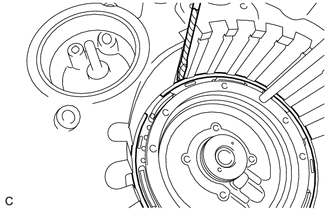
REMOVE 1ST AND REVERSE BRAKE PISTON
-

Apply compressed air (approximately 392 kPa (4.0 kgf/cm2, 57 psi)) to the ATF hole to remove the 1st and reverse brake piston from the automatic transaxle case sub-assembly.
-
Remove the 2 O-rings from the 1st and reverse brake piston.
-
-
REMOVE MANUAL VALVE LEVER SHAFT OIL SEAL
-
Using a screwdriver with its tip wrapped with protective tape, remove the manual valve lever shaft oil seal from the automatic transaxle case sub-assembly.
Note
Be careful not to damage the automatic transaxle case sub-assembly.
-
-
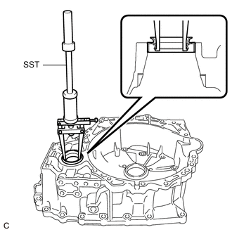
REMOVE TRANSAXLE CASE OIL SEAL
-
Using SST, remove the transaxle case oil seal from the transaxle housing.
- SST
- 09308-36010
Note
Be careful not to damage the transaxle housing.
-
-
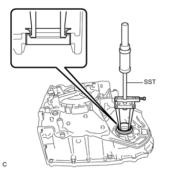
REMOVE FRONT DRIVE SHAFT OIL SEAL RH
-
Using SST, remove the front drive shaft oil seal RH from the transaxle housing.
- SST
- 09308-36010
Note
Be careful not to damage the transaxle housing.
-
-
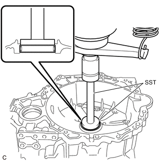
REMOVE FRONT DRIVE SHAFT OIL SEAL LH
-
Using SST, remove the front drive shaft oil seal LH from the automatic transaxle case sub-assembly.
- SST
- 09308-36010
Note
Be careful not to damage the automatic transaxle case sub-assembly.
-
-
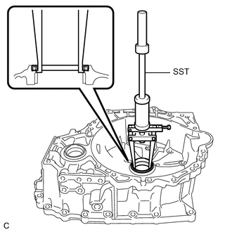
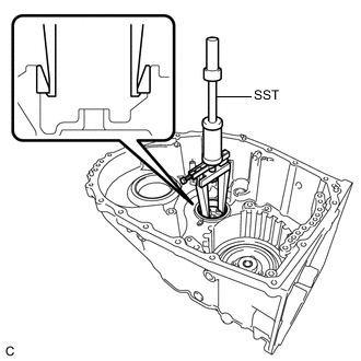
REMOVE NEEDLE ROLLER BEARING
-
Using SST and a press, remove the needle roller bearing from the transaxle housing.
- SST
- 09950-60010 ( 09951-00550 )
- 09950-70010 ( 09951-07200 )
Note
Be careful not to damage the transaxle housing.
-
-
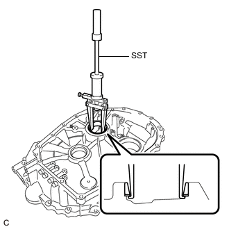
REMOVE COUNTER DRIVEN GEAR REAR TAPERED ROLLER BEARING (OUTER RACE)
-
Using SST, remove the counter driven gear rear tapered roller bearing (outer race) from the automatic transaxle case sub-assembly.
- SST
- 09308-36010
Note
Be careful not to damage the automatic transaxle case sub-assembly.
Tech Tips
Align the claw of the SST with the indentation of the automatic transaxle case sub-assembly when removing the parts.
-
-
REMOVE COUNTER DRIVEN GEAR REAR TAPERED ROLLER BEARING (INNER RACE)
-
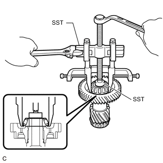
Using SST, remove the counter driven gear rear tapered roller bearing (inner race) from the pinion and counter driven gear sub-assembly.
- SST
- 09950-40011 ( 09951-04010, 09952-04010, 09953-04030, 09954-04010, 09955-04011, 09957-04010, 09958-04011 )
- 09950-60010 ( 09951-00310 )
Note
Because SST is attached to the roller portion, there is a possibility that the roller portion could break and SST could come off before the counter driven gear rear tapered roller bearing (inner race) comes off.
-
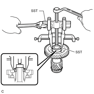
If the roller portion breaks and SST comes off, reattach SST to the inner race in the position shown in the illustration, and continue removing the parts.
- SST
- 09950-40011 ( 09951-04010, 09952-04010, 09953-04030, 09954-04010, 09955-04011, 09957-04010, 09958-04011 )
- 09950-60010 ( 09951-00310 )
-
-
REMOVE COUNTER DRIVEN GEAR FRONT TAPERED ROLLER BEARING (OUTER RACE)
-
Using SST, remove the counter driven gear front tapered roller bearing (outer race) and pinion and counter driven gear shim from the transaxle housing.
- SST
- 09308-36010
Note
Be careful not to damage the transaxle housing.
Tech Tips
Align the claw of the SST with the indentation of the transaxle housing when removing the parts.
-
-
REMOVE COUNTER DRIVEN GEAR FRONT TAPERED ROLLER BEARING (INNER RACE)
-
Using SST, remove the counter driven gear front tapered roller bearing (inner race) from the pinion and counter driven gear sub-assembly.
- SST
- 09950-00020
- 09950-00030
- 09950-60010 ( 09951-00380 )
-
-
REMOVE FRONT DIFFERENTIAL CASE REAR TAPERED ROLLER BEARING (OUTER RACE)
-
REMOVE FRONT DIFFERENTIAL CASE REAR TAPERED ROLLER BEARING (INNER RACE)
-
REMOVE FRONT DIFFERENTIAL CASE FRONT TAPERED ROLLER BEARING (OUTER RACE)
-
REMOVE FRONT DIFFERENTIAL CASE FRONT TAPERED ROLLER BEARING (INNER RACE)
-
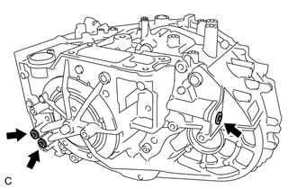
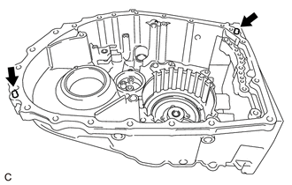
REMOVE NO. 1 TRANSAXLE CASE PLUG
-
Remove the 4 No. 1 transaxle case plugs from the automatic transaxle case sub-assembly.
-
Remove the 4 No. 1 transaxle case plugs from the transaxle housing.
-
Remove the 8 O-rings from the 8 No. 1 transaxle case plugs.
-
-
REMOVE NO. 2 TRANSAXLE CASE PLUG
-
Using a 6 mm socket hexagon wrench, remove the 3 No. 2 transaxle case plugs and 3 gaskets from the automatic transaxle case sub-assembly.
-
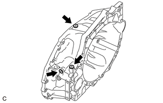
Using a 6 mm socket hexagon wrench, remove the 3 No. 2 transaxle case plugs and 3 gaskets from the transaxle housing.
-
-
REMOVE AUTOMATIC TRANSMISSION CASE STRAIGHT PIN
Note
It is not necessary to remove the automatic transmission case straight pins unless they are being replaced.
-
Remove the 2 automatic transmission case straight pins from the automatic transaxle case sub-assembly.
-
-
REMOVE NO. 1 BREATHER PLUG (ATM)
-
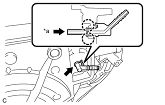
*a Push Disengage each claw and remove the No. 1 breather plug (ATM) from the automatic transaxle case sub-assembly.
Note
Be careful not to damage the automatic transaxle case sub-assembly.
-