OIL COOLER INSTALLATION

PROCEDURE
-
INSTALL TRANSMISSION OIL COOLER
-
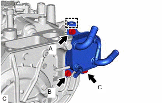
Engage the hook and temporarily install the transmission oil cooler to the automatic transaxle case sub-assembly with the bolt (A).
-
Install the bolt (B).
- Torque:
- 13.5 N*m { 138 kgf*cm, 10 ft.*lbf }
-
Install the bolt (C).
- Torque:
- 13.5 N*m { 138 kgf*cm, 10 ft.*lbf }
-
Fully tighten the bolt (A) to install the transmission oil cooler.
- Torque:
- 13.5 N*m { 138 kgf*cm, 10 ft.*lbf }
-
-
CONNECT WATER BY-PASS HOSE ASSEMBLY
-
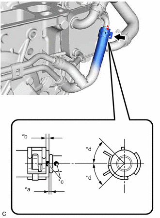
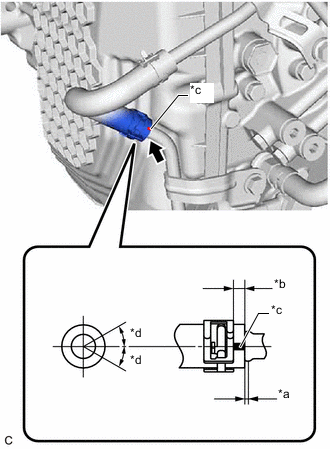
Connect the water by-pass hose assembly to the transmission oil cooler and slide the clip to secure it.
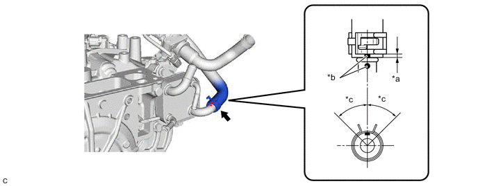
*a 2 to 7 mm (0.0787 to 0.276 in.) *b Paint Mark *c 45° (Claw of Clip Location) - - Note
-
Make sure to slide the water by-pass hose assembly until it contacts the hose stopper of the transmission oil cooler.
-
Make sure to align the paint mark of the water by-pass hose assembly with the paint mark of the transmission oil cooler.
-
Make sure that the claws of the clip are within the location shown in the illustration.
-
-
-
CONNECT NO. 1 WATER BY-PASS HOSE
-
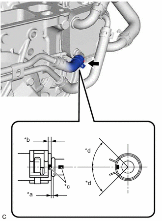
Connect the No. 1 water by-pass hose to the transmission oil cooler and slide the clip to secure it.
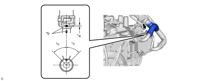
*a 2 to 7 mm (0.0787 to 0.276 in.) *b Paint Mark *c 45° (Claw of Clip Location) - - Note
-
Make sure to slide the No. 1 water by-pass hose until it contacts the hose stopper of the transmission oil cooler.
-
Make sure to align the paint mark of the No. 1 water by-pass hose with the paint mark of the transmission oil cooler.
-
Make sure that the claws of the clip are within the location shown in the illustration.
-
-
Engage the 3 clamps to install the transmission breather clamp.
-
-
INSTALL NO. 1 OIL COOLER TUBE SUB-ASSEMBLY WITHOUT HOSE
-
Install the inlet No. 1 oil cooler hose, inlet No. 2 oil cooler hose, outlet No. 1 oil cooler hose and outlet No. 2 oil cooler hose to the No. 1 oil cooler tube sub-assembly without hose and slide the 4 clips to secure them.
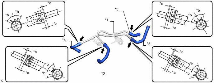
*1 No. 1 Oil Cooler Tube Sub-assembly without Hose *2 Inlet No. 1 Oil Cooler Hose *3 Inlet No. 2 Oil Cooler Hose *4 Outlet No. 1 Oil Cooler Hose *5 Outlet No. 2 Oil Cooler Hose - - *a 2 to 7 mm (0.0787 to 0.276 in.) *b 45° (Claw of Clip Location) *c 0 to 3 mm (0 to 0.118 in.) - - Note
-
Make sure to slide the inlet No. 1 oil cooler hose, inlet No. 2 oil cooler hose, outlet No. 1 oil cooler hose and outlet No. 2 oil cooler hose until each contacts the hose stopper of the No. 1 oil cooler tube sub-assembly without hose.
-
Make sure that the claws of each clip are within the location shown in the illustration.
-
-
*a 0 to 3 mm (0 to 0.118 in.) *b 2 to 7 mm (0.0787 to 0.276 in.) *c Paint Mark *d 45° (Claw of Clip Location) Connect the outlet No. 2 oil cooler hose to the transmission oil cooler and slide the clip to secure it.
Note
-
Make sure to slide the outlet No. 2 oil cooler hose until it contacts the hose stopper of the transmission oil cooler.
-
Make sure to align the paint mark of the outlet No. 2 oil cooler hose with the paint mark of the transmission oil cooler.
-
Make sure that the claws of the clip are within the location shown in the illustration.
-
-
*a 0 to 3 mm (0 to 0.118 in.) *b 2 to 7 mm (0.0787 to 0.276 in.) *c Paint Mark *d 45° (Claw of Clip Location) Connect the inlet No. 2 oil cooler hose to the transmission oil cooler and slide the clip to secure it.
Note
-
Make sure to slide the inlet No. 2 oil cooler hose until it contacts the hose stopper of the transmission oil cooler.
-
Make sure to align the paint mark of the inlet No. 2 oil cooler hose with the paint mark of the transmission oil cooler.
-
Make sure that the claws of the clip are within the location shown in the illustration.
-
-
Temporarily install the No. 1 oil cooler tube sub-assembly without hose to the automatic transaxle case sub-assembly with the 2 bolts.
-
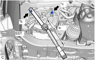
*a Torque Wrench Fulcrum Length *b Bolt (A) *c Bolt (B) Using SST, tighten the bolt (A).
- SST
- 09961-00950
- Torque:
- Specified tightening torque
- 13.5 N*m { 138 kgf*cm, 10 ft.*lbf }
Tech Tips
-
Calculate the torque wrench reading when changing the fulcrum length of the torque wrench.
-
When using SST (fulcrum length of 150 mm (5.91 in.)) + torque wrench (fulcrum length of 162 mm (6.38 in.)):
7.0 N*m (71 kgf*cm, 62 in.*lbf)
-
Tighten the bolt (B).
- Torque:
- 13.5 N*m { 138 kgf*cm, 10 ft.*lbf }
-
-
CONNECT INLET NO. 1 OIL COOLER HOSE
-
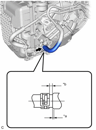
*a 0 to 3 mm (0 to 0.118 in.) *b 2 to 7 mm (0.0787 to 0.276 in.) Connect the inlet No. 1 oil cooler hose to the No. 1 oil cooler outlet tube sub-assembly and slide the clip to secure it.
Note
Make sure to slide the inlet No. 1 oil cooler hose until it contacts the hose stopper of the No. 1 oil cooler outlet tube sub-assembly.
-
-
CONNECT OUTLET NO. 1 OIL COOLER HOSE
-
*a 0 to 3 mm (0 to 0.118 in.) *b 2 to 7 mm (0.0787 to 0.276 in.) *c Paint Mark (Left Side of Vehicle) *d 30° (Paint Mark Location) Connect the outlet No. 1 oil cooler hose to the oil cooler union sub-assembly and slide the clip to secure it.
Note
-
Make sure to slide the outlet No. 1 oil cooler hose until it contacts the hose stopper of the oil cooler union sub-assembly.
-
Make sure that the paint mark of the outlet No. 1 oil cooler hose is within the location shown in the illustration.
-
-
-
INSTALL BATTERY CLAMP SUB-ASSEMBLY
-
INSTALL ECM
-
INSTALL BATTERY
-
ADD ENGINE COOLANT
-
ADJUST AUTOMATIC TRANSAXLE FLUID
-
INSPECT FOR OIL LEAK
-
INSPECT FOR COOLANT LEAK
-
INSTALL FRONT FENDER APRON SEAL LH
-
INSTALL NO. 2 ENGINE UNDER COVER ASSEMBLY
-
INSTALL NO. 1 ENGINE UNDER COVER
-
INSTALL FRONT WHEEL OPENING EXTENSION PAD LH
-
INSTALL FRONT WHEEL OPENING EXTENSION PAD RH
-
INSTALL FRONT WHEEL LH