VEHICLE PROXIMITY NOTIFICATION SYSTEM TERMINALS OF ECU
-
CHECK VEHICLE APPROACHING SPEAKER CONTROLLER

-
Disconnect the O33 vehicle approaching speaker controller connector.
-
Measure the voltage according to the value(s) in the table below.
Terminal No. (Symbol) Wiring Color Terminal Description Condition Specified Condition O33-1 (IG) - Body ground R - Body ground IG power supply Power switch on (IG) 11 to 14 V Power switch off Below 1 V If the result is not as specified, there may be a malfunction in the wire harness.
-
Measure the resistance according to the value(s) in the table below.
Terminal No. (Symbol) Wiring Color Terminal Description Condition Specified Condition O33-7 (GND) - Body ground W-B - Body ground Ground Always Below 1 Ω If the result is not as specified, there may be a malfunction in the wire harness.
-
Reconnect the O33 vehicle approaching speaker controller connector.
-
Measure the voltage and check for pulses according to the value(s) in the table below.
Terminal No. (Symbol) Wiring Color Terminal Description Condition Specified Condition O33-2 (STP) - O33-7 (GND) B - W-B Stop light signal input Power switch off, brake pedal depressed 8 V or higher Power switch off, brake pedal released Below 1 V O33-3 (SP+) - O33-8 (SP-) P - V Vehicle approaching speaker output Vehicle approaching speaker operating A waveform synchronized with the sound is output.
(See Waveform 1)
O33-5 (SW) - O33-7 (GND) L - W-B Vehicle approaching speaker switch signal input Power switch on (IG), vehicle approaching speaker switch not pressed Below 1 V Power switch on (IG), vehicle approaching speaker switch pressed 6 V or higher O33-6 (SPD) - O33-7 (GND) L - W-B Speed signal input Power switch on (IG), wheel being rotated Pulse generation
(See Waveform 2)
O33-9 (PRST) - O33-7 (GND) W - W-B SIL communication signal Power switch on (IG), during transmission Pulse generation
(See Waveform 3)
O33-10 (IND) - O33-7 (GND) SB - W-B Warning signal output Approximately 3 seconds after turning power switch on (IG) Below 1.8 V O33-11 (KOK) - O33-7 (GND) P - W-B Permission signal Power switch on (READY), shift lever in P Below 2.3 V Power switch on (READY), engine stopped and shift lever not in P 8 V or higher If the result is not as specified, there is a problem in the vehicle approaching speaker controller or wire harness.
-
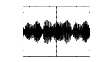
Waveform 1
Item Condition Tool setting 1 V/DIV., 200 ms./DIV. Vehicle condition Vehicle approaching speaker operating -
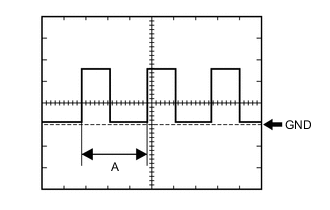
Waveform 2
Item Condition Tool setting 5 V/DIV., 20 ms./DIV. Vehicle condition Power switch on (IG), wheel being rotated Tech Tips
When the system is functioning normally, one wheel revolution generates 4 pulses. As the vehicle speed increases, the width indicated by (A) in the illustration narrows.
-
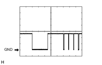
Waveform 3
Item Condition Tool setting 5 V/DIV., 10 ms./DIV. Vehicle condition Power switch on (IG), during transmission
-
-
-
CHECK HYBRID VEHICLE CONTROL ECU ASSEMBLY
-
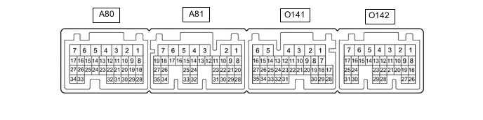
Disconnect the A80, A81 and O141 power management control ECU connectors.
-
Measure the voltage according to the value(s) in the table below.
Terminal No. (Symbol) Wiring Color Terminal Description Condition Specified Condition A80-1 (+B2) - O141-6 (E1) W - W-B IG power supply Power switch on (IG) 11 to 14 V Power switch off Below 1 V A81-1 (IG2) - O141-6 (E1) W - W-B IG power supply Power switch on (IG) 11 to 14 V Power switch off Below 1 V A81-3 (+B1) - O141-6 (E1) W - W-B IG power supply Power switch on (IG) 11 to 14 V Power switch off Below 1 V If the result is not as specified, there may be a malfunction in the wire harness.
-
Measure the resistance according to the value(s) in the table below.
Terminal No. (Symbol) Wiring Color Terminal Description Condition Specified Condition O141-6 (E1) - Body ground W-B - Body ground Ground Always Below 1 Ω If the result is not as specified, there may be a malfunction in the wire harness.
-
Reconnect the A80, A81 and O141 hybrid vehicle control ECU assembly connectors.
-
Measure the voltage according to the value(s) in the table below.
Terminal No. (Symbol) Wiring Color Terminal Description Condition Specified Condition O141-7 (KOK) - O141-6 (E1) R - W-B Permission signal Power switch on (READY), shift lever in P Below 2.3 V Power switch on (READY), engine stopped and shift lever not in P 8 V or higher If the result is not as specified, there is a problem in the hybrid vehicle control ECU assembly or wire harness.
-