CLEARANCE LIGHT ASSEMBLY INSPECTION
PROCEDURE
-
INSPECT CLEARANCE LIGHT ASSEMBLY LH (for Triple Beam Headlight)
-
Remove the clearance light assembly LH.
-
Remove the clearance light LED unit assembly LH from the clearance light assembly LH.
-
Measure the resistance according to the value(s) in the table below.
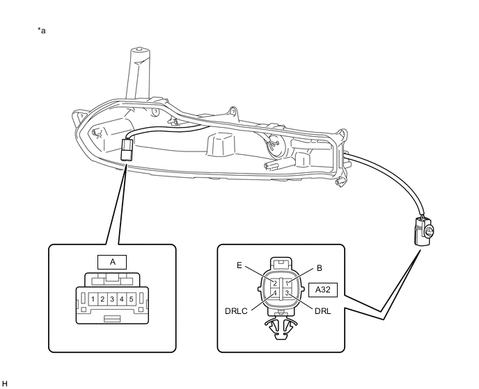
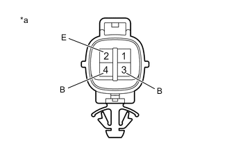
*a Component without harness connected
(Clearance Light Assembly LH)
- - Standard Resistance Tester Connection Condition Specified Condition A32-1 (B) - A-5 Always Below 1 Ω A32-2 (E) - A-2 Always Below 1 Ω A32-3 (DRL) - A-4 Always Below 1 Ω A32-4 (DRLC) - A-3 Always Below 1 Ω If the result is not as specified, replace the clearance light assembly LH.
-
Install the clearance light LED unit assembly LH to the clearance light assembly LH.
-
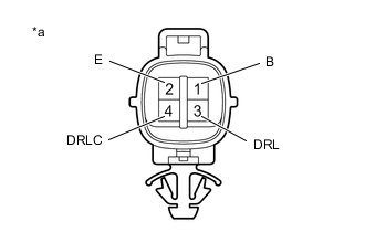
*a Component without harness connected
(Clearance Light Assembly LH)
Apply auxiliary battery voltage to the clearance light assembly LH and check the light comes on.
OK Condition Specified Condition Auxiliary battery positive (+) → 3 (DRL)
Auxiliary battery negative (-) → 2 (E) and 4 (DRLC)
Light comes on Auxiliary battery positive (+) → 1 (B)
Auxiliary battery negative (-) → 2 (E)
Light comes on If the result is not as specified, replace the clearance light LED unit assembly.
-
-
INSPECT CLEARANCE LIGHT ASSEMBLY RH (for Triple Beam Headlight)
-
Remove the clearance light assembly RH.
-
Remove the clearance light LED unit assembly RH from the clearance light assembly RH.
-
Measure the resistance according to the value(s) in the table below.

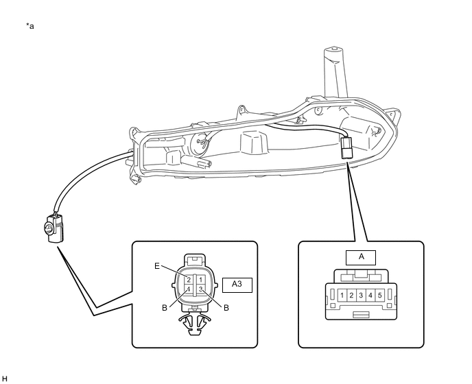
*a Component without harness connected
(Clearance Light Assembly RH)
- - Standard Resistance Tester Connection Condition Specified Condition A3-1 (B) - A-5 Always Below 1 Ω A3-2 (E) - A-2 Always Below 1 Ω A3-3 (DRL) - A-4 Always Below 1 Ω A3-4 (DRLC) - A-3 Always Below 1 Ω If the result is not as specified, replace the clearance light assembly RH.
-
Install the clearance light LED unit assembly RH to the clearance light assembly RH.
-

*a Component without harness connected
(Clearance Light Assembly RH)
Apply auxiliary battery voltage to the clearance light assembly RH and check the light comes on.
OK Condition Specified Condition Auxiliary battery positive (+) → 3 (DRL)
Auxiliary battery negative (-) → 2 (E) and 4 (DRLC)
Light comes on Auxiliary battery positive (+) → 1 (B)
Battery negative (-) → 2 (E)
Light comes on If the result is not as specified, replace the clearance light assembly RH.
-
-
INSPECT CLEARANCE LIGHT ASSEMBLY LH (for Single Beam Headlight)
-
Remove the clearance light assembly LH.
-
Remove the clearance light LED unit assembly LH from the clearance light assembly LH.
-
Measure the resistance according to the value(s) in the table below.
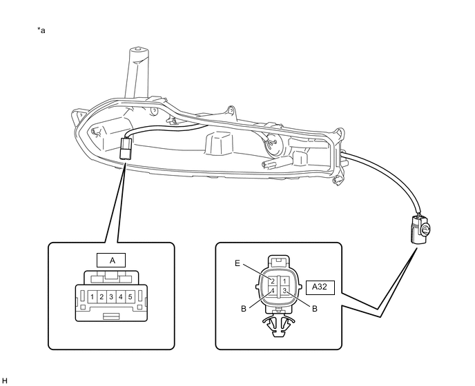
*a Component without harness connected
(Clearance Light Assembly LH)
- - Standard Resistance Tester Connection Condition Specified Condition A32-2 (E) - A-2 Always Below 1 Ω A32-3 (B) - A-4 Always Below 1 Ω A32-4 (B) - A-3 Always Below 1 Ω If the result is not as specified, replace the clearance light assembly LH.
-
Install the clearance light LED unit assembly LH to the clearance light assembly LH.
-

*a Component without harness connected
(Clearance Light Assembly LH)
Apply auxiliary battery voltage to the clearance light assembly LH and check the light comes on.
OK Condition Specified Condition Auxiliary battery positive (+) → 4 (B)
Auxiliary battery negative (-) → 2 (E)
Light comes on Auxiliary battery positive (+) → 3 (B)
Auxiliary battery negative (-) → 2 (E)
Light comes on If the result is not as specified, replace the clearance light LED unit assembly LH.
-
-
INSPECT CLEARANCE LIGHT ASSEMBLY RH (for Single Beam Headlight)
-
Remove the clearance light assembly RH.
-
Remove the clearance light LED unit assembly RH from the clearance light assembly RH.
-
Measure the resistance according to the value(s) in the table below.
*a Component without harness connected
(Clearance Light Assembly RH)
- - Standard Resistance Tester Connection Condition Specified Condition A3-2 (E) - A-2 Always Below 1 Ω A3-3 (B) - A-4 Always Below 1 Ω A3-4 (B) - A-3 Always Below 1 Ω If the result is not as specified, replace the clearance light assembly RH.
-
Install the clearance light LED unit assembly RH to the clearance light assembly RH.
-
*a Component without harness connected
(Clearance Light Assembly RH)
Apply auxiliary battery voltage to the clearance light assembly RH and check the light comes on.
OK Condition Specified Condition Auxiliary battery positive (+) → 4 (B)
Auxiliary battery negative (-) → 2 (E)
Light comes on Auxiliary battery positive (+) → 3 (B)
Auxiliary battery negative (-) → 2 (E)
Light comes on If the result is not as specified, replace the clearance light LED unit assembly RH.
-