CAN COMMUNICATION SYSTEM Radio Receiver Assembly Communication Stop Mode
DESCRIPTION
| Detection Item | Symptom | Trouble Area |
|---|---|---|
| Radio Receiver Assembly Communication Stop Mode | Either condition is met:
|
|
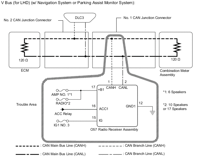
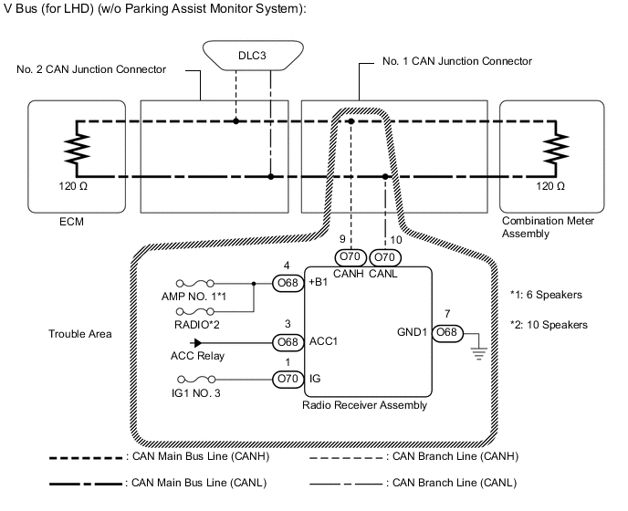
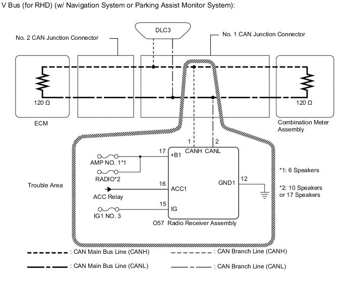
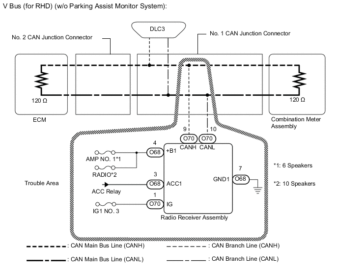
WIRING DIAGRAM
CAUTION / NOTICE / HINT
Note
-
Before measuring the resistance of the CAN bus, turn the power switch off and leave the vehicle for 1 minute or more without operating the key or any switches, or opening or closing the doors. After that, disconnect the cable from the negative (-) auxiliary battery terminal and leave the vehicle for 1 minute or more before measuring the resistance.
-
After turning the power switch off, waiting time may be required before disconnecting the cable from the negative (-) auxiliary battery terminal. Therefore, make sure to read the disconnecting the cable from the negative (-) auxiliary battery terminal notices before proceeding with work.
-
Because the order of diagnosis is important to allow correct diagnosis, make sure to begin troubleshooting using How to Proceed with Troubleshooting when CAN communication system related DTCs are output.
-
After performing repairs, perform the DTC check procedure and confirm that the DTCs are not output again.
-
DTC check procedure: Turn the power switch on (IG) and wait at least 30 seconds.
-
After the repair, perform the CAN bus check and check that all the ECUs and sensors connected to the CAN communication system are displayed.
-
Inspect the fuses for circuits related to this system before performing the following procedure.
Tech Tips
-
Operating the power switch, any other switches or a door triggers related ECU and sensor communication on the CAN. This communication will cause the resistance value to change.
-
Even after DTCs are cleared, if a DTC is stored again after driving the vehicle for a while, the malfunction may be occurring due to vibration of the vehicle. In such a case, wiggling the ECUs or wire harness while performing the inspection below may help determine the cause of the malfunction.
PROCEDURE
-
CHECK VEHICLE TYPE
-
Check vehicle type.
Result Result Proceed to w/ Navigation System or Parking Assist Monitor System A w/o Parking Assist Monitor System B
B 
CHECK FOR OPEN IN CAN BUS LINES (RADIO RECEIVER ASSEMBLY BRANCH LINE) Click here
A 
-
-
CHECK FOR OPEN IN CAN BUS LINES (RADIO RECEIVER ASSEMBLY BRANCH LINE)
-
Disconnect the cable from the negative (-) auxiliary battery terminal.
-
Disconnect the O57 radio receiver assembly connector.
-
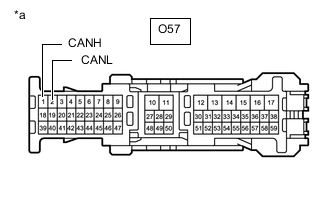
*a Front view of wire harness connector
(to Radio Receiver Assembly)
Measure the resistance according to the value(s) in the table below.
Standard Resistance Tester Connection Condition Specified Condition O57-1 (CANH) - O57-2 (CANL) Cable disconnected from negative (-) auxiliary battery terminal 54 to 69 Ω Result Result OK NG
NG 
REPAIR OR REPLACE CAN BRANCH LINE OR CONNECTOR (RADIO RECEIVER ASSEMBLY)
OK
-
-
CHECK HARNESS AND CONNECTOR (POWER SOURCE CIRCUIT)
-
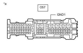
*a Front view of wire harness connector
(to Radio Receiver Assembly)
Measure the resistance according to the value(s) in the table below.
Standard Resistance Tester Connection Condition Specified Condition O57-12 (GND1) - Body ground Cable disconnected from negative (-) auxiliary battery terminal Below 1 Ω -
Reconnect the cable to the negative (-) auxiliary battery terminal.
-
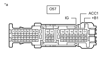
*a Front view of wire harness connector
(to Radio Receiver Assembly)
Measure the voltage according to the value(s) in the table below.
Standard Voltage Tester Connection Condition Specified Condition O57-15 (IG) - Body ground Power switch ON (IG) 11 to 14 V O57-16 (ACC1) - Body ground Power switch ON (ACC) 11 to 14 V O57-17 (+B1) - Body ground Power switch off 11 to 14 V Result Result Result OK(w/ Navigation System) A OK(w/ Parking Assist Monitor System) B NG C
A
REPLACE RADIO RECEIVER ASSEMBLY Click here
B
REPLACE RADIO RECEIVER ASSEMBLY Click here
C
REPAIR OR REPLACE HARNESS OR CONNECTOR (POWER SOURCE CIRCUIT)
-
-
CHECK FOR OPEN IN CAN BUS LINES (RADIO RECEIVER ASSEMBLY BRANCH LINE)
-
Disconnect the cable from the negative (-) auxiliary battery terminal.
-
Disconnect the O70 radio receiver assembly connector.
-
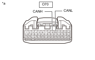
*a Front view of wire harness connector
(to Radio Receiver Assembly)
Measure the resistance according to the value(s) in the table below.
Standard Resistance Tester Connection Condition Specified Condition O70-9 (CANH) - O70-10 (CANL) Cable disconnected from negative (-) auxiliary battery terminal 54 to 69 Ω Result Result OK NG
NG
REPAIR OR REPLACE CAN BRANCH LINE OR CONNECTOR (RADIO RECEIVER ASSEMBLY)
OK
-
-
CHECK HARNESS AND CONNECTOR (POWER SOURCE CIRCUIT)
-
Disconnect the O68 radio receiver assembly connector.
-
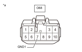
*a Front view of wire harness connector
(to Radio Receiver Assembly)
Measure the resistance according to the value(s) in the table below.
Standard Resistance Tester Connection Condition Specified Condition O68-7 (GND1) - Body ground Cable disconnected from negative (-) auxiliary battery terminal Below 1 Ω -
Reconnect the cable to the negative (-) auxiliary battery terminal.
-
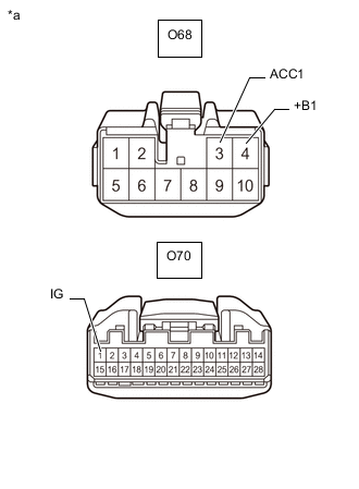
*a Front view of wire harness connector
(to Radio Receiver Assembly)
Measure the voltage according to the value(s) in the table below.
Standard Voltage Tester Connection Condition Specified Condition O68-3 (ACC1) - Body ground Power switch on (ACC) 11 to 14 V O68-4 (+B1) - Body ground Power switch off 11 to 14 V O70-1 (IG) - Body ground Power switch on (IG) 11 to 14 V Result Result OK NG
OK
REPLACE RADIO RECEIVER ASSEMBLY Click here
NG
REPAIR OR REPLACE HARNESS OR CONNECTOR (POWER SOURCE CIRCUIT)
-