INTEGRATION RELAY INSPECTION
PROCEDURE
-
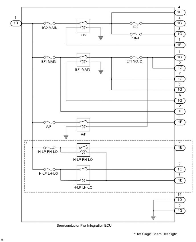
INSPECT SEMICONDUCTOR PWR INTEGRATION ECU
-
IG2-MAIN RELAY:
-
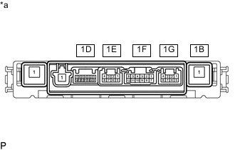
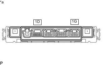
*a Component without harness connected
(Semiconductor Pwr Integration ECU)
Measure the resistance according to the value(s) in the table below.
Standard Resistance Tester Connection Condition Specified Condition 1B-1 - 1F-4 Auxiliary battery voltage is not applied between terminals 1E-1 and 1D-14 10 kΩ or higher 1B-1 - 1G-3 1B-1 - 1G-4 1B-1 - 1F-4 Auxiliary battery positive (+) → 1E-1
Auxiliary battery negative (-) → 1D-14
Below 1 Ω 1B-1 - 1G-3 1B-1 - 1G-4 If the result is not as specified, replace the semiconductor pwr integration ECU.
-
-
EFI-MAIN RELAY:
-

*a Component without harness connected
(Semiconductor Pwr Integration ECU)
Measure the resistance according to the value(s) in the table below.
Standard Resistance Tester Connection Condition Specified Condition 1B-1 - 1G-1 Auxiliary battery voltage is not applied between terminals 1G-6 and 1D-14 10 kΩ or higher 1B-1 - 1G-2 1B-1 - 1G-7 1B-1 - 1G-8 1F-2 - 1G-1 1B-1 - 1G-1 Auxiliary battery positive (+) → 1G-6
Auxiliary battery negative (-) → 1D-14
Below 1 Ω 1B-1 - 1G-2 1B-1 - 1G-7 1B-1 - 1G-8 1F-2 - 1G-1 If the result is not as specified, replace the semiconductor pwr integration ECU.
-
-
A/F RELAY:
-
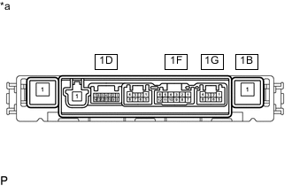
*a Component without harness connected
(Semiconductor Pwr Integration ECU)
Measure the resistance according to the value(s) in the table below.
Standard Resistance Tester Connection Condition Specified Condition 1B-1 - 1F-1 Auxiliary battery voltage is not applied between terminals 1G-1 and 1D-14 10 kΩ or higher 1B-1 - 1F-1 Auxiliary battery positive (+) → 1G-1
Auxiliary battery negative (-) → 1D-14
Below 1 Ω If the result is not as specified, replace the semiconductor pwr integration ECU.
-
-
H-LP RH-LO RELAY:
-

*a Component without harness connected
(Semiconductor Pwr Integration ECU)
Measure the resistance according to the value(s) in the table below.
Standard Resistance Tester Connection Condition Specified Condition 1B-1 - 1E-2 Auxiliary battery voltage is not applied between terminals 1B-1 and 1D-8 10 kΩ or higher -
Measure the voltage according to the value(s) in the table below.
Standard Voltage Tester Connection Condition Specified Condition 1E-2 - Auxiliary battery negative (-) Auxiliary battery positive (+) → 1B-1
Auxiliary battery negative (-) → 1D-8
11 to 14 V If the result is not as specified, replace the semiconductor pwr integration ECU.
-
-
H-LP LH-LO RELAY:
-
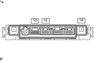
*a Component without harness connected
(Semiconductor Pwr Integration ECU)
Measure the resistance according to the value(s) in the table below.
Standard Resistance Tester Connection Condition Specified Condition 1B-1 - 1E-3 Auxiliary battery voltage is not applied between terminals 1B-1 and 1D-8 10 kΩ or higher -
Measure the voltage according to the value(s) in the table below.
Standard Voltage Tester Connection Condition Specified Condition 1E-3 - Auxiliary battery negative (-) Auxiliary battery positive (+) → 1B-1
Auxiliary battery negative (-) → 1D-8
11 to 14 V If the result is not as specified, replace the semiconductor pwr integration ECU.
-
-
Semiconductor pwr integration ECU ground:
-
*a Component without harness connected
(Semiconductor Pwr Integration ECU)
Measure the resistance according to the value(s) in the table below.
Standard Resistance Tester Connection Condition Specified Condition 1D-14 - 1G-5 Always Below 1 Ω If the result is not as specified, replace the semiconductor pwr integration ECU.
-
-