PARKING ASSIST MONITOR SYSTEM(w/o Parallel Parking Assist Function) TERMINALS OF ECU
-
REAR TELEVISION CAMERA ASSEMBLY
-
Disconnect the z22 rear television camera assembly connector.

-
Measure the voltage on the wire harness side connector according to the value(s) in the table below.
Terminal No. (Symbol) Wiring Color Terminal Description Condition Specified Condition z22-6 (CB+) - Body ground R - Body ground Power source Power switch on (ACC) 5.8 to 6.5 V If the result is not as specified, there may be a malfunction on the wire harness side.
-
Reconnect the z22 rear television camera assembly connector.
-
Check for pulses between each terminal of the connector.
Terminal No. (Symbol) Wiring Color Terminal Description Condition Specified Condition z22-3 (CV+) - z22-2 (CV-) Y - BR Video signal Power switch on (IG)
Shift lever in R
Camera lens not covered, displaying image
Pulse generation
(Refer to waveform 1)
Power switch on (IG)
Shift lever in R
Camera lens covered, blacking out screen
Pulse generation
(Refer to waveform 2)
z22-5 (CGND) - Body ground GR - Body ground Camera ground Always Below 1 V Tech Tips
A waterproof connector is used for the rear television camera assembly. Therefore, inspect the waveform at the multi-display assembly with the connector connected.
If the result is not as specified, the rear television camera assembly may be malfunctioning.
-
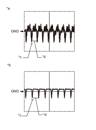
*a Waveform 1 (camera lens is not covered, displaying an image) *b Waveform 2 (camera lens is covered, blacking out the screen) *c Synchronization Signal *d Video Waveform Reference (Oscilloscope waveform):
Tech Tips
A waterproof connector is used for the rear television camera assembly. Therefore, inspect the waveform at the multi-display assembly with the connector connected.
-
Waveform 1 (camera lens is not covered, displaying an image)
Item Content Measurement terminal z22-3 (CV+) - z22-2 (CV-) Measurement setting 200 mV/DIV., 50 μs./DIV. Condition Power switch on (IG), shift lever in R Tech Tips
-
The video waveform changes according to the image sent by the rear television camera assembly.
-
The video waveform is constantly output when the power switch is on (ACC).
-
-
Waveform 2 (camera lens is covered, blacking out the screen)
Item Content Measurement terminal z22-3 (CV+) - z22-2 (CV-) Measurement setting 200 mV/DIV., 50 μs./DIV. Condition Power switch on (IG), shift lever in R Tech Tips
-
The video waveform changes according to the image sent by the rear television camera assembly.
-
The video waveform is constantly output when the power switch is on (ACC).
-
-
-
-
MULTI-DISPLAY ASSEMBLY
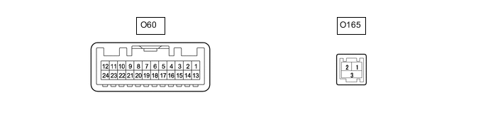
Terminal No. (Symbol) Wiring Color Terminal Description Condition Specified Condition O60-13 (GND1) - Body ground W-B - Body ground Ground Always Below 1 Ω O60-9 (V-) - O60-13 (GND1) W - W-B Video signal ground Always Below 1 Ω O60-8 (V+) - O60-9 (V-) R - W-B Video signal Camera lens not covered, displaying image
Power switch on (IG), shift lever in R
Pulse generation
(Refer to waveform 1)
Camera lens covered, blacking out screen
Power switch on (IG), shift lever in R
Pulse generation
(Refer to waveform 2)
O60-21 (CGND) - Body ground - Shield ground Power switch off Below 1 Ω O60-10 (CA+) - O60-13 (GND1) B - W-B Power source Always 5.8 to 6.5 V O60-3 (REV) - O60-13 (GND1) R - W-B Reverse signal Power switch on (IG), shift lever in R 9 to 16 V Power switch on (IG), shift lever not in R Below 2 V
-
Reference (Oscilloscope waveform):
-
*a Waveform 1 (camera lens is not covered, displaying an image) *b Waveform 2 (camera lens is covered, blacking out the screen) *c Synchronization Signal *d Video Waveform Waveform 1 (camera lens not covered, displaying an image)
Item Content Measurement terminal O60-8 (V+) - O60-9 (V-) Measurement setting 200 mV/DIV., 50 μs/DIV. Condition Power switch on (IG), shift lever in R Tech Tips
-
The video waveform changes according to the image sent by the rear television camera assembly.
-
The video waveform is constantly output when the power switch is on (ACC).
-
-
Waveform 2 (camera lens covered, blacking out the screen)
Item Content Measurement terminal O60-8 (V+) - O60-9 (V-) Measurement setting 200 mV/DIV., 50 μs/DIV. Condition Power switch on (IG), shift lever in R Tech Tips
-
The video waveform changes according to the image sent by the rear television camera assembly.
-
The video waveform is constantly output when the power switch is on (ACC).
-
-
-