PARKING ASSIST MONITOR SYSTEM(w/o Parallel Parking Assist Function) SYSTEM DESCRIPTION
-
GENERAL
-
This system has a rear television camera assembly mounted on the luggage compartment door to display an image of the area behind the vehicle on the multi-display assembly. The multi-display assembly also shows a composite view consisting of the area behind the vehicle and parking guide lines to assist the driver in parking the vehicle by monitoring the area behind the vehicle.
-
This system consists of the following components:
-
Rear Television camera assembly
-
Luggage electrical key switch
-
Radio receiver assembly
-
Multi-display assembly
-
Spiral cable with sensor sub-assembly
-
Hybrid vehicle control ECU assembly
-
Main body ECU (multiplex network body ECU)
-
Blind spot monitor sensor LH*1
-
Clearance warning ECU assembly*2
-
*1: w/ Blind Spot Monitor System
-
*2: w/ LEXUS Parking Assist-sensor System
-
-
-
This system is equipped with a self-diagnosis system, which is operated on a designated window that appears on the multi-display assembly.
-
-
FUNCTION OF COMPONENTS
-
The rear television camera assembly controls the system by using information from the following components.
Item Function Rear Television Camera Assembly
-
Mounted on the luggage compartment door to transmit a composite image of the area behind the vehicle and guide lines calculated based on signals received from each ECU, to the multi-display assembly.
-
Has a color video camera that uses a Complementary Metal Oxide Semiconductor (CMOS) and wide-angle lens.
-
Stops displaying the guide lines when an open signal is received for the luggage compartment door.
-
Performs overall control of the system by receiving signals from the sensor and ECUs.
Multi-display Assembly
-
Receives video signals which contain a composite image of the area behind the vehicle taken with the rear television camera assembly and guide lines calculated based on signals received from each ECU.
-
Performs control of the system by receiving the reverse signal from the BKUP LP relay.
-
Receives diagnostic mode video signals from the rear television camera assembly.
-
Displays "You can not calibrate the camera when the door is open. Please close the door." on the back camera position setting screen when the luggage compartment door is open.
Radio Receiver Assembly Transmits a setting information signal to the rear television camera assembly via CAN communication. Spiral Cable with Sensor Sub-assembly Detects the angle of the steering wheel and transmits the resulting signals to the rear television camera assembly via CAN communication. Hybrid Vehicle Control ECU Assembly
-
Transmits the vehicle information signal to the rear television camera assembly via CAN communication.
-
Transmits the reverse signal to the multi-display assembly and the radio receiver assembly via CAN communication.
Main Body ECU (Multiplex Network Body ECU) Transmits the luggage compartment door courtesy switch signal and vehicle information signal to the rear television camera assembly and the radio receiver assembly via CAN communication. Blind Spot Monitor Sensor LH*1 Transmits the RCTA information signal to the rear television camera assembly via CAN communication. Clearance Warning ECU Assembly*2 Transmits the sonar information signal to the rear television camera assembly via CAN communication.
-
*1: w/ Blind Spot Monitor System
-
*2: w/ LEXUS Parking Assist-sensor System
-
-
-
OPERATION EXPLANATION
-
Operation description of the park assist monitor system
-
The multi-display assembly receives the reverse signal when the power switch is on (IG) and the shift lever is moved to R. After receiving the reverse signal, the multi-display assembly switches to the parking assist monitor system.
-
-
-
DISPLAY MODE
-
Rear view screen
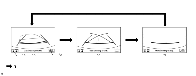
*a Guide Line Display Mode Switching Button *b Estimated Course Line Display Mode *c Parking Assist Guide Line Display Mode *d Distance Guide Line Display Mode *e Display Mode Switching Button *f Guide Line Display Mode Switching Button Pressed Tech Tips
The screen changes to the wide rear view screen when the display mode switching button is selected.
-
While the parking assist monitor is displayed on the multi-display assembly, pressing the guide line display mode switching button switches the parking assist monitor display mode.
Parking Assist Monitor Display Mode Parking Assist Monitor Display Mode Distance Guide Lines
(Red)
Estimated Course Lines
(Yellow)
Distance Guide Line
(Yellow)
Vehicle Width Extension Guide Line
(Blue)
Distance Guide Line
(Blue)
Parking Assist Guide Lines
(Blue)
Vehicle Center Line
(Blue)
Estimated course line display mode Displayed Displayed Displayed Displayed Displayed Not displayed Displayed Parking assist guide line display mode Displayed Not displayed Not displayed Displayed Not displayed Displayed Displayed Distance guide line display mode Displayed Not displayed Not displayed Not displayed Not displayed Not displayed Not displayed
-
-
Wide rear view screen
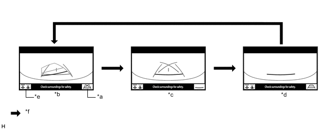
*a Guide Line Display Mode Switching Button *b Estimated Course Line Display Mode *c Parking Assist Guide Line Display Mode *d Distance Guide Line Display Mode *e Display Mode Switching Button *f Guide Line Display Mode Switching Button Pressed Tech Tips
The screen changes to the rear view screen when the display mode switching button is selected.
-
While the parking assist monitor is displayed on the multi-display assembly , pressing the guide line display mode switching button switches the parking assist monitor display mode.
Parking Assist Monitor Display Mode Parking Assist Monitor Display Mode Distance Guide Lines
(Red)
Estimated Course Lines
(Yellow)
Distance Guide Line
(Yellow)
Vehicle Width Extension Guide Line
(Blue)
Distance Guide Line
(Blue)
Parking Assist Guide Lines
(Blue)
Vehicle Center Line
(Blue)
Estimated course line display mode Displayed Displayed Displayed Displayed Displayed Not displayed Displayed Parking assist guide line display mode Displayed Not displayed Not displayed Displayed Not displayed Displayed Displayed Distance guide line display mode Displayed Not displayed Not displayed Not displayed Not displayed Not displayed Not displayed
-
-
-
DIAGNOSTIC FUNCTION OUTLINE
-
This parking assist monitor system has a diagnostic function displayed on the multi-display assembly . This function enables calibration (adjustment and verification) of the parking assist monitor system.
-
The following items for the parking assist monitor system can be checked using the GTS.
Item Proceed to DTC Data List / Active Test
-