AUDIO AND VISUAL SYSTEM(w/ Parking Assist Monitor System) Switch Operation of Remote Touch not Accepted
CAUTION / NOTICE / HINT
Note
Depending on the parts that are replaced during vehicle inspection or maintenance, performing initialization, registration or calibration may be needed. Refer to Precaution for Audio and Visual System.
PROCEDURE
-
START DIAGNOSTIC MODE
-
Enter diagnostic mode and check if the "Service Menu" screen can be displayed.
OK Diagnostic mode can be activated. Result Proceed to OK NG
NG 
REMOTE TOUCH SELF CHECK (SWITCH OPERATION CHECK) Click here
OK 
-
-
CHECK PANEL SWITCH (OPERATION CHECK)
-
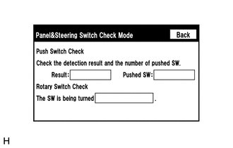
Enter the "Panel&Steering Switch Check Mode" screen. Refer to Check Panel & Steering Switch in Operation Check.
-
Operate the abnormal switch and check if the switch status is correctly displayed.
OK The switch status is correctly displayed as operated. Result Proceed to OK NG
OK 
REPLACE RADIO RECEIVER ASSEMBLY Click here
NG
-
-
REMOTE TOUCH SELF CHECK (SWITCH OPERATION CHECK)
-
Activate self-diagnostic mode.
-
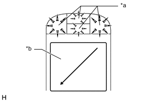
*a Switch Illumination *b Touchpad Check switch operation.
-
Operate the touchpad diagonally from the upper right to the lower left to turn the switch illumination off.
Note
Since the touchpad may recognize a pinch in/out or flick operation if operated with 2 fingers, always use 1 finger to operate the touchpad in self-diagnostic mode.
-
With the switch illumination turned off, press each switch of the remote touch (remote operation controller assembly) and check that the switch illumination turns on.
Result Result Proceed to Self-diagnostic mode cannot be activated. A Some switches do not turn on the switch illumination when they are pressed. All switches turn on the switch illumination when they are pressed. B
-
A
REPLACE REMOTE TOUCH (REMOTE OPERATION CONTROLLER ASSEMBLY) Click here
B
REPLACE RADIO RECEIVER ASSEMBLY Click here
-