BRAKE STROKE SIMULATOR CYLINDER INSTALLATION
CAUTION / NOTICE / HINT
Tech Tips
-
Use the same procedure for LHD and RHD.
-
The following procedure is for LHD.
PROCEDURE
-
INSTALL BRAKE STROKE SIMULATOR CYLINDER SUB-ASSEMBLY
-
Install the brake stroke simulator cylinder sub-assembly to the brake master cylinder sub-assembly with the 2 bolts.
- Torque:
- 8.0 N*m { 82 kgf*cm, 71 in.*lbf }
-
-
INSTALL BRAKE STROKE SIMULATOR TUBE
-
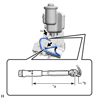
*a Torque Wrench Fulcrum Length *b Union Nut Wrench Using a union nut wrench, install the brake stroke simulator tube to the brake stroke simulator cylinder sub-assembly and brake master cylinder sub-assembly.
- Torque:
- Specified tightening torque
- 15.2 N*m { 155 kgf*cm, 11 ft.*lbf }
Note
-
Do not kink or damage the brake stroke simulator tube.
-
Do not allow any foreign matter such as dirt or dust to enter the brake stroke simulator tube from the connecting parts.
Tech Tips
-
Calculate the torque wrench reading when changing the fulcrum length of the torque wrench.
-
When using a union nut wrench (fulcrum length of 22 mm (0.866 in.)) + torque wrench (fulcrum length of 162 mm (6.38 in.)):
13.38 N*m (136 kgf*cm, 10 ft.*lbf)
-
-
INSTALL BRAKE MASTER WITH STROKE SIMULATOR CYLINDER ASSEMBLY
for LHD: Click here
for RHD: Click here