REAR COIL SPRING REMOVAL

CAUTION / NOTICE / HINT
Tech Tips
-
Use the same procedure for the RH side and LH side.
-
The following procedure is for the LH side.
PROCEDURE
-
REMOVE REAR WHEEL
-
REMOVE REAR SUSPENSION ARM COVER
-
SEPARATE REAR HEIGHT CONTROL SENSOR SUB-ASSEMBLY
-
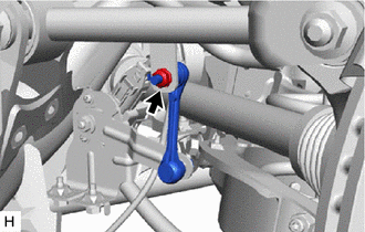
Remove the nut and separate the rear height control sensor sub-assembly from the rear No. 1 upper control arm assembly.
-
-
REMOVE TOE CONTROL LINK SUB-ASSEMBLY
-
SEPARATE REAR NO. 1 SUSPENSION ARM ASSEMBLY
-
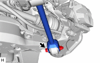
Remove the bolt and nut, and separate the rear No. 1 suspension arm assembly from the rear axle assembly.
Note
Because the nut has its own stopper, do not turn the nut. Loosen the bolt with the nut secured.
-
-
REMOVE REAR STABILIZER LINK ASSEMBLY
-
SEPARATE REAR SHOCK ABSORBER ASSEMBLY
-
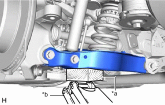
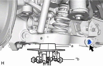
*a Wooden Block *b Jack Support the rear No. 2 suspension arm assembly using a jack and wooden block.
Note
-
When jacking up the rear No. 2 suspension arm assembly, be sure to jack it up slowly.
-
Make sure to perform this operation with the vehicle kept as low as possible.
-
-
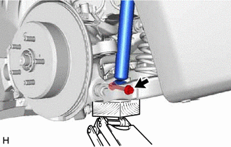
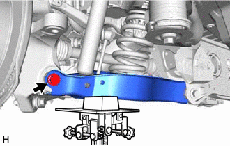
Remove the bolt and nut, and separate the rear shock absorber assembly from the rear No. 2 suspension arm assembly.
Note
Because the nut has its own stopper, do not turn the nut. Loosen the bolt with the nut secured.
-
-
REMOVE REAR COIL SPRING
-
*a Wooden Block *b Transmission Jack Support the rear No. 2 suspension arm assembly using a transmission jack and wooden block.
CAUTION:
Do not jack up the rear No. 2 suspension arm assembly too high as the vehicle may fall.
Note
-
When jacking up the rear No. 2 suspension arm assembly, be sure to jack it up slowly.
-
Make sure to perform this operation with the vehicle kept as low as possible.
-
-
Loosen the rear No. 2 suspension arm assembly with the bolt (rear suspension member sub-assembly side).
Note
-
Because the nut has its own stopper, do not turn the nut. Loosen the bolt with the nut secured.
-
Do not remove the bolt and nut.
-
-
Loosen the rear No. 2 suspension arm assembly with the bolt (rear axle assembly side).
Note
-
Because the nut has its own stopper, do not turn the nut. Loosen the bolt with the nut secured.
-
Do not remove the bolt and nut.
-
-
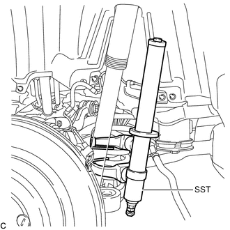
Attach the hooks of each SST arm across the diameter of the rear coil spring.
- SST
- 09727-30022 ( 09727-00010, 09727-00031 )
- 09727-00120
CAUTION:
-
Make sure that the hooks of the upper and lower arms are attached to the coil spring so that the distance between the hooks is as large as possible.
-
Check that the claws of the hooks are securely attached to the coil spring.
-
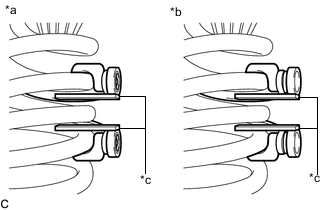
*a Correct *b Incorrect *c Stopper plate Install the stopper plates to the hooks of SST.
CAUTION:
Make sure that the stopper plates are installed securely.
-
Using SST, compress the rear coil spring.
CAUTION:
-
If the coil spring bends while using SST, stop immediately and reattach SST correctly.
-
Do not compress the coil spring to the point where the coils touch each other.
-
Do not use an impact wrench.
-
Compress the rear coil spring until there is no tension between the vehicle body and rear coil spring.
-
-
Remove the bolt and nut, and separate the rear No. 2 suspension arm assembly from the rear axle assembly.
Note
Because the nut has its own stopper, do not turn the nut. Loosen the bolt with the nut secured.
-
Slowly lower the rear No. 2 suspension arm assembly, and remove the rear coil spring with SST and rear upper coil spring insulator.
-
Remove SST from the rear coil spring.
Note
Do not use an impact wrench. It will damage SST.
-
-
REMOVE REAR UPPER COIL SPRING INSULATOR
-
Remove the rear upper coil spring insulator from the rear coil spring.
-
-
REMOVE REAR LOWER COIL SPRING INSULATOR
-
Remove the rear lower coil spring insulator from the rear No. 2 suspension arm assembly.
-