REAR LOWER ARM REMOVAL
CAUTION / NOTICE / HINT
Tech Tips
-
Use the same procedure for the RH side and LH side.
-
The following procedure is for the LH side.
PROCEDURE
-
REMOVE REAR WHEEL
-
REMOVE REAR SUSPENSION ARM COVER
-
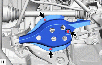
Remove the 3 bolts and rear suspension arm cover from the rear No. 2 suspension arm assembly.
-
-
SEPARATE REAR HEIGHT CONTROL SENSOR SUB-ASSEMBLY
-
REMOVE TOE CONTROL LINK SUB-ASSEMBLY
-
REMOVE REAR NO. 1 SUSPENSION ARM ASSEMBLY
-
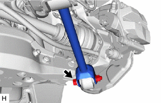
Remove the bolt and nut, and separate the rear No. 1 suspension arm assembly from the rear axle assembly.
Note
Because the nut has its own stopper, do not turn the nut. Loosen the bolt with the nut secured.
-
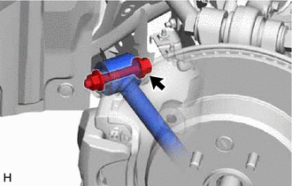
Remove the bolt and nut, and remove the rear No. 1 suspension arm assembly from the rear suspension member sub-assembly.
Note
Because the nut has its own stopper, do not turn the nut. Loosen the bolt with the nut secured.
-
-
REMOVE REAR STABILIZER LINK ASSEMBLY
-
SEPARATE REAR SHOCK ABSORBER ASSEMBLY
-
REMOVE REAR COIL SPRING
-
REMOVE REAR UPPER COIL SPRING INSULATOR
-
REMOVE REAR LOWER COIL SPRING INSULATOR
-
REMOVE REAR NO. 2 SUSPENSION ARM ASSEMBLY
-
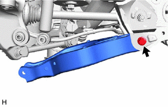
Remove the bolt, nut and rear No. 2 suspension arm assembly from the rear suspension member sub-assembly.
Note
Because the nut has its own stopper, do not turn the nut. Loosen the bolt with the nut secured.
-