STEERING KNUCKLE REMOVAL

CAUTION / NOTICE / HINT
Note
When removing or installing the front disc brake caliper assembly, pushing back the disc brake piston may cause a large clearance between the brake pads and brake disc. When the brake pedal is depressed with a large clearance between the brake pads and the brake disc, DTCs C1341, C1342, C1343 and/or C1344 related to abnormal brake fluid pressure may be stored. Make sure to clear the DTCs after performing this step.
Tech Tips
-
Use the same procedure for the RH side and LH side.
-
The following procedure is for the LH side.
PROCEDURE
-
REMOVE ABS MOTOR RELAY
for LHD: Click here
for RHD: Click here
-
REMOVE FRONT WHEEL
-
DISCONNECT FRONT SKID CONTROL SENSOR WIRE
-
SEPARATE FRONT DISC BRAKE CALIPER ASSEMBLY
-
REMOVE FRONT DISC
-
REMOVE FRONT AXLE HUB SUB-ASSEMBLY
-
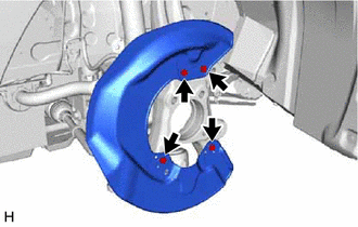
REMOVE FRONT DISC BRAKE DUST COVER
-
Remove the 4 bolts and front disc brake dust cover from the steering knuckle.
-
-
SEPARATE FRONT LOWER BALL JOINT ASSEMBLY
-
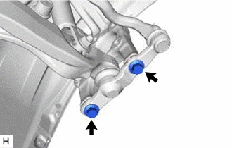
Remove the 2 bolts and separate the front lower ball joint assembly from the steering knuckle.
-
-
REMOVE STEERING KNUCKLE
-
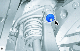
Remove the clip and nut.
-
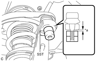
*a 1 mm (0.0394 in.) Install SST to the front upper suspension arm assembly as shown in the illustration.
- SST
- 09960-20010 ( 09961-02060 )
Note
Check that the clearance measurement between SST and the steering knuckle is 1 mm (0.0394 in.).
-
Using SST, remove the steering knuckle from the front upper suspension arm assembly as shown in the illustration.
- SST
- 09960-20010 ( 09961-02010 )
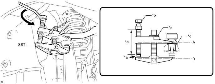
*a Molybdenum Grease Application Area *b Place wrench here *c Center Nut *d Spacer *e String - - CAUTION:
Apply molybdenum grease to the threads and end of the SST bolt.
Note
-
Install SST with the center nut so that (A) and (B) shown in the illustration are parallel. Otherwise, the front upper suspension arm dust cover may be damaged.
-
Be sure to place a wrench on the part indicated in the illustration.
-
Do not damage the ball joint dust cover.
-
Do not damage the steering knuckle.
-
Make sure that SST is securely positioned on the spacer.
-
Be sure to tighten the string firmly to secure SST to the front upper suspension arm assembly to prevent SST from falling off.
Tech Tips
If the steering knuckle spacer has come off, replace the steering knuckle with a new one.
-