LANE DEPARTURE ALERT SYSTEM(w/ Steering Control) Power Source Circuit
DESCRIPTION
This circuit provides power to operate the forward recognition camera.
WIRING DIAGRAM
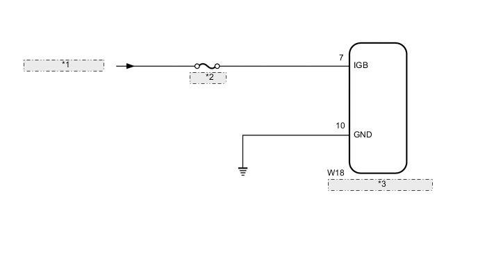
| *1 | from IG1 NO. 3 Relay |
| *2 | IG1 NO. 3 |
| *3 | Forward Recognition Camera |
CAUTION / NOTICE / HINT
Note
Inspect the fuses for circuits related to this system before performing the following procedure.
PROCEDURE
-
CHECK HARNESS AND CONNECTOR (POWER SOURCE VOLTAGE)
-
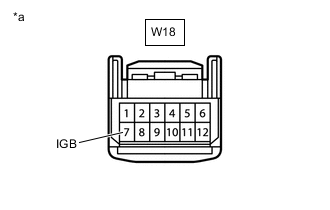
*a Front view of wire harness connector
(to Forward Recognition Camera)
Disconnect the W18 forward recognition camera connector.
-
Turn the power switch on (IG).
-
Measure the voltage according to the value(s) in the table below.
Standard Voltage Tester Connection Condition Specified Condition W18-7 (IGB) - Body ground Power switch on (IG) 11 to 14 V -
Turn the power switch off.
-
Connect the W18 forward recognition camera connector.
Result Proceed to OK NG
NG 
REPAIR OR REPLACE HARNESS OR CONNECTOR
OK 
-
-
CHECK HARNESS AND CONNECTOR (FORWARD RECOGNITION CAMERA - BODY GROUND)
-
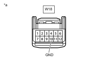
*a Front view of wire harness connector
(to Forward Recognition Camera)
Disconnect the W18 forward recognition camera connector.
-
Measure the resistance according to the value(s) in the table below.
Standard Resistance Tester Connection Condition Specified Condition W18-10 (GND) - Body ground Always Below 1 Ω -
Connect the W18 forward recognition camera connector
Result Proceed to OK NG
OK
PROCEED TO NEXT SUSPECTED AREA SHOWN IN PROBLEM SYMPTOMS TABLE Click here
NG
REPAIR OR REPLACE HARNESS OR CONNECTOR
-