LANE RECOGNITION CAMERA SENSOR ADJUSTMENT

CAUTION / NOTICE / HINT
Tech Tips
If the lane departure warning camera is replaced or removed and installed, or the toe-in is adjusted, perform lane departure warning camera adjustment.
PROCEDURE
-
ADJUST LANE DEPARTURE WARNING CAMERA (for LHD)
-
Prepare for camera axis learning.
-
Move the vehicle to a level surface.
-
Make sure the engine oil in the vehicle is at the specified level.
-
Make sure the engine coolant in the vehicle is at the specified level.
-
Make sure the fuel tank is full.
-
Make sure the spare tire is in the vehicle.
-
Make sure the standard tools are in the vehicle.
-
Make sure no one is in the vehicle.
-
Make sure no extra loads are in the vehicle.
-
Adjust the tire pressures to the specified pressure.
-
Clean the windshield.
-
-
Perform front wheel alignment adjustment.
-
Perform front wheel alignment adjustment.
Note
Perform this procedure as accurately as possible.
-
-
Perform rear wheel alignment adjustment.
-
Perform rear wheel alignment adjustment.
Note
Perform this procedure as accurately as possible.
-
-
Create a target sheet.
-
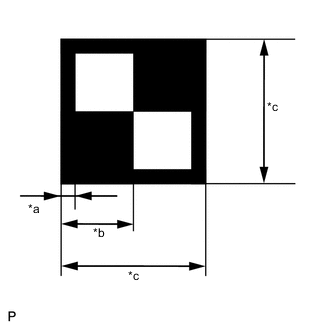
*a 16 mm (0.630 in.) *b 80 mm (3.15 in.) *c 160 mm (6.30 in.) Print or copy the illustration. Check that the dimensions are within +/- 5 mm (0.197 in.) of the ones in the following table.
Note
-
Make sure that the black areas of the target sheet are not glossy.
-
Make sure that the borders of the black and white areas on the target sheet are straight, and are not warped or blurry.
If the dimensions of the print or copy are not as specified, adjust settings and reprint or recopy so that the dimensions are as specified.

-
-
-
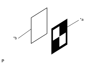
*a Target Sheet *b Cardboard Attach the target sheet.
-
Place the prepared target sheet on a piece of cardboard of the same size with the black area at the top right, as shown in the illustration. Then use double-sided tape to secure the target sheet in place.
Note
Do not attach reflective tape, such as transparent adhesive tape, to the target face, as this may affect target recognition.
-
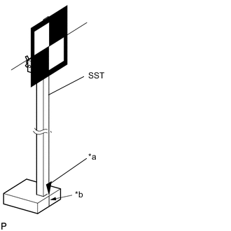
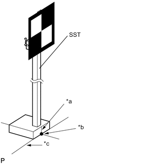
*a Pointed Tip Weight *b Mark-off Line Hang a weight with a pointed tip from the center of the target sheet. Then, with double-sided tape, attach the target sheet to the reflector so that the weight aligns with the mark-off line of SST (laser radar adjusting reflector).
- SST
- 09870-60000 ( 09870-60010, 09870-60020 )
Note
-
Perform this procedure as accurately as possible.
-
Attach the target sheet so that it is horizontal with the ground.
-
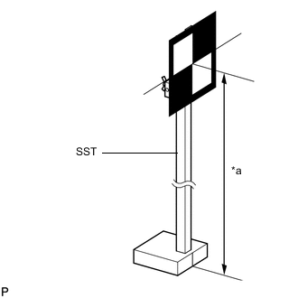
*a 1350 mm (4.43 ft.) Move the reflector up or down to position the center of the target at the height shown in the illustration and secure it in place.
- SST
- 09870-60000 ( 09870-60010, 09870-60020 )
Note
Perform this procedure as accurately as possible.
-
-
Measure the target placement point.
Note
-
Do not place black and white patterned objects near the target.
-
Face the vehicle toward a wall with no patterns or make sure the background behind the target has no patterns.
-
Perform this procedure as accurately as possible.
-
Do not place reflective materials in the area behind the target.
-
Make sure the distance between the target and wall is within 3 m (9.84 ft.).
-
Make sure the shadow of the target is not on the wall as this may cause a recognition error.
-
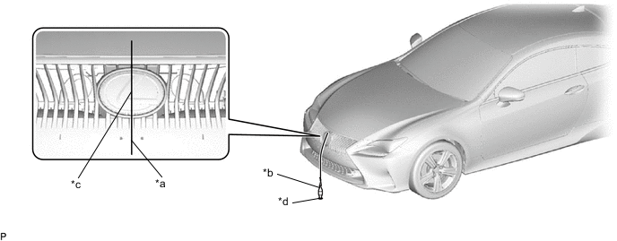
Hang a string (with weight) from the center of the vehicle rear emblem. Mark the rear center point of the vehicle on the ground.
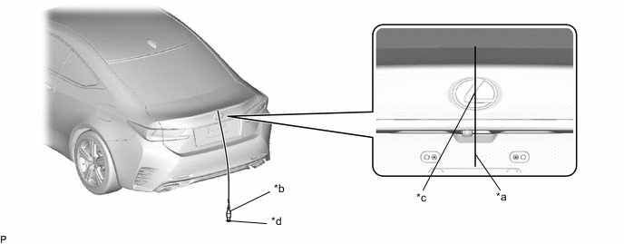
*a String *b Weight *c Center point *d Point A -
Repeat for the front of the vehicle.
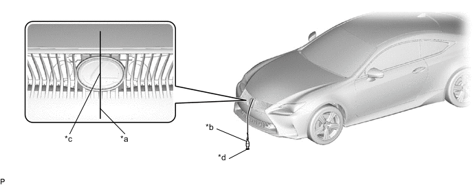
*a String *b Weight *c Center point *d Point B -
Using tape and a string, create a line that connects point B to point A and extends at least 2000 mm (6.56 ft.) beyond the vehicle front center point.
Tech Tips
-
Make sure the string is taut (using tape, etc.) when it is secured.
-
Lightly flick the string with your fingers several times to confirm that the string is aligned with point B.
-
-
Mark point C at a position 332 mm (1.09 ft.) in front of point B.
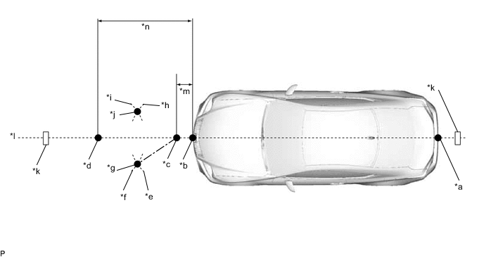
*a Point A *b Point B *c Point C *d Point D *e Line E *f Line F *g Point G (Placement Point 2) *h Line H *i Line I *j Point J (Placement Point 3) *k Tape *l String *m 332 mm (1.09 ft.) *n 1582 mm (5.19 ft.) -
Mark point D at a position 1582 mm (5.19 ft.) in front of point B.
-
Using a string, mark line E at a position 1000 mm (3.28 ft.) from point C.
-
Using a string, mark line H at a position 1000 mm (3.28 ft.) from point C.
-
Using a string, mark line F at a position 1000 mm (3.28 ft.) from point D.
-
Using a string, mark line I at a position 1000 mm (3.28 ft.) from point D.
-
Mark point G (placement point 2) at the point where line E and line F intersect.
-
Mark point J (placement point 3) at the point where line H and line I intersect.
-
Using tape and a string, create a line that connects point G and point J (target placement line).
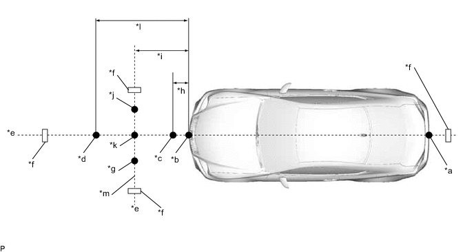
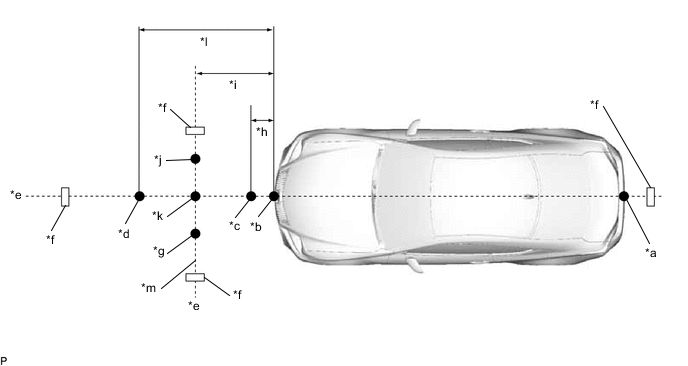
*a Point A *b Point B *c Point C *d Point D *e String *f Tape *g Point G (Placement Point 2) *h 332 mm (1.09 ft.) *i 957 mm (3.14 ft.) *j Point J (Placement Point 3) *k Point K (Placement Point 1) *l 1582 mm (5.19 ft.) *m Target Placement Line - - -
Mark point K (placement point 1) at the intersection between the string connecting points C and D and the string connecting points G and J.
-
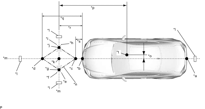
Confirm the distance measurements for points K, G, and J (placement points 1, 2, and 3).
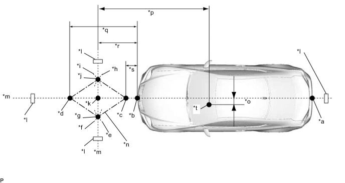
*a Point A *b Point B *c Point C *d Point D *e Line E *f Line F *g Point G (Placement Point 2) *h Line H *i Line I *j Point J (Placement Point 3) *k Point K (Placement Point 1) *l Tape *m String *n 1000 mm (3.28 ft.) (String) *o 55 mm (2.17 in.) *p 3000 mm (9.84 ft.) *q 1582 mm (5.19 ft.) *r 957 mm (3.14 ft.) *s 332 mm (1.09 ft.) *t Lane Departure Warning Camera Position
-
-
Memorize camera/target position.
Note
-
Close all doors.
-
Perform the procedure with no one in the vehicle.
-
During the procedure, do not lean on the vehicle.
-
Do not turn on the headlights.
-
When using the GTS:
-
Connect the GTS to the DLC3.
-
Turn the power switch on (IG).*1
-
Turn the GTS on.
-
Enter the following menus: Chassis / Lane Departure Alert / Utility.
-
Follow the GTS display, and continue with the adjustment.
Chassis > Lane Departure Alert > UtilityTester Display Recognition Camera/Target Position Memory -
-
Input the height of the camera "1252 mm (49.3 in.)" and the horizontal position of the camera "-55 mm (-2.17 in.)" into the input screen. Then press the "Next" button on the display screen.
-
Input "3000 mm (118 in.)" for the distance from the camera to the target and "1350 mm (53.1 in.)" for the height of the target into the input screen. Then press the "Next" button on the display screen.
-
Input "1840 mm (72.4 in.)" for the width of the vehicle and "1111 mm (43.7 in.)" for the distance between the recognition camera and the front tire into the input screen. Then press the "Next" button on the display screen.
-
Press the "Exit" button to finish the camera/target position memory mode.
Note
If "Error Camera/target position memory" is displayed on the screen, press the "Try Again" button, and repeat from procedure *1.
-
-
Perform camera axis learning.
-
Enter the following menus: Chassis / Lane Departure Alert / Utility.*1
-
Follow the GTS display and continue with the adjustment.
Chassis > Lane Departure Alert > UtilityTester Display Recognition Camera Axis Adjust -
*a Mark-off Line *b Point K (Placement Point 1) *c Target Placement Line Align the target sheet with the target placement line and align the mark-off line with point K (placement point 1).
-
Check that the screen displays camera axis learning for target 1, then press the "Next" button on the display screen.
-
*a Mark-off Line *b Point G (Placement Point 2) *c Target Placement Line Align the target sheet with the target placement line, and align the mark-off line with point G (placement point 2).
-
Check that the screen displays camera axis learning for target 2, then press the "Next" button on the display screen.
Note
Within 3 minutes after the screen displays the camera axis learning for target 2, move the target and press the "Next" button on the display screen.
-
*a Mark-off Line *b Point J (Placement Point 3) *c Target Placement Line Align the target sheet with the target placement line and align the mark-off line with point J (placement point 3).
-
Check that the screen displays camera axis learning for target 3 then press the "Next" button on the display screen.
Note
Within 3 minutes after the screen displays the camera axis learning for target 3, move the target and press the "Next" button on the display screen.
-
Press the "Exit" button to finish camera axis learning mode.
Note
If "Error camera axis adjust" is displayed on the screen, press the "Exit" button. Confirm the following conditions then turn the power switch on (IG) and off, and repeat from procedure *1.
-
The height of the target is correct.
-
The distance from the lane departure warning camera to the target is correct.
-
The orientation of the target is correct (black area positioned at the top right).
-
The surrounding area is sufficiently bright.
-
Black and white patterned objects are not placed near the target.
-
-
-
-
ADJUST LANE DEPARTURE WARNING CAMERA (for RHD)
-
Prepare for camera axis learning.
-
Move the vehicle to a level surface.
-
Make sure the engine oil in the vehicle is at the specified level.
-
Make sure the engine coolant in the vehicle is at the specified level.
-
Make sure the fuel tank is full.
-
Make sure the spare tire is in the vehicle.
-
Make sure the standard tools are in the vehicle.
-
Make sure no one is in the vehicle.
-
Make sure no extra loads are in the vehicle.
-
Adjust the tire pressures to the specified pressure.
-
Clean the windshield.
-
-
Perform front wheel alignment adjustment.
-
Perform front wheel alignment adjustment.
Note
Perform this procedure as accurately as possible.
-
-
Perform rear wheel alignment adjustment.
-
Perform rear wheel alignment adjustment.
Note
Perform this procedure as accurately as possible.
-
-
Create a target sheet.
-
*a 16 mm (0.630 in.) *b 80 mm (3.15 in.) *c 160 mm (6.30 in.) Print or copy the illustration. Check that the dimensions are within +/- 5 mm (0.197 in.) of the ones in the following table.
Note
-
Make sure that the black areas of the target sheet are not glossy.
-
Make sure that the borders of the black and white areas on the target sheet are straight, and are not warped or blurry.
If the dimensions of the print or copy are not as specified, adjust settings and reprint or recopy so that the dimensions are as specified.
-
-
-
*a Target Sheet *b Cardboard Attach the target sheet.
-
Place the prepared target sheet on a piece of cardboard of the same size with the black area at the top right, as shown in the illustration. Then use double-sided tape to secure the target sheet in place.
Note
Do not attach reflective tape, such as transparent adhesive tape, to the target face, as this may affect target recognition.
-
*a Pointed Tip Weight *b Mark-off Line Hang a weight with a pointed tip from the center of the target sheet. Then, with double-sided tape, attach the target sheet to the reflector so that the weight aligns with the mark-off line of SST (laser radar adjusting reflector).
- SST
- 09870-60000 ( 09870-60010, 09870-60020 )
Note
-
Perform this procedure as accurately as possible.
-
Attach the target sheet so that it is horizontal with the ground.
-
*a 1350 mm (4.43 ft.) Move the reflector up or down to position the center of the target at the height shown in the illustration and secure it in place.
- SST
- 09870-60000 ( 09870-60010, 09870-60020 )
Note
Perform this procedure as accurately as possible.
-
-
Measure the target placement point.
Note
-
Do not place black and white patterned objects near the target.
-
Face the vehicle toward a wall with no patterns or make sure the background behind the target has no patterns.
-
Perform this procedure as accurately as possible.
-
Do not place reflective materials in the area behind the target.
-
Make sure the distance between the target and wall is within 3 m (9.84 ft.).
-
Make sure the shadow of the target is not on the wall as this may cause a recognition error.
-
Hang a string (with weight) from the center of the vehicle rear emblem. Mark the rear center point of the vehicle on the ground.
*a String *b Weight *c Center point *d Point A -
Repeat for the front of the vehicle.
*a String *b Weight *c Center point *d Point B -
Using tape and a string, create a line that connects point B to point A and extends at least 2000 mm (6.56 ft.) beyond the vehicle front center point.
Tech Tips
-
Make sure the string is taut (using tape, etc.) when it is secured.
-
Lightly flick the string with your fingers several times to confirm that the string is aligned with point B.
-
-
Mark point C at a position 332 mm (1.09 ft.) in front of point B.

*a Point A *b Point B *c Point C *d Point D *e Line E *f Line F *g Point G (Placement Point 2) *h Line H *i Line I *j Point J (Placement Point 3) *k Tape *l String *m 332 mm (1.09 ft.) *n 1582 mm (5.19 ft.) -
Mark point D at a position 1582 mm (5.19 ft.) in front of point B.
-
Using a string, mark line E at a position 1000 mm (3.28 ft.) from point C.
-
Using a string, mark line H at a position 1000 mm (3.28 ft.) from point C.
-
Using a string, mark line F at a position 1000 mm (3.28 ft.) from point D.
-
Using a string, mark line I at a position 1000 mm (3.28 ft.) from point D.
-
Mark point G (placement point 2) at the point where line E and line F intersect.
-
Mark point J (placement point 3) at the point where line H and line I intersect.
-
Using tape and a string, create a line that connects point G and point J (target placement line).
*a Point A *b Point B *c Point C *d Point D *e String *f Tape *g Point G (Placement Point 2) *h 332 mm (1.09 ft.) *i 957 mm (3.14 ft.) *j Point J (Placement Point 3) *k Point K (Placement Point 1) *l 1582 mm (5.19 ft.) *m Target Placement Line - - -
Mark point K (placement point 1) at the intersection between the string connecting points C and D and the string connecting points G and J.
-
Confirm the distance measurements for points K, G, and J (placement points 1, 2, and 3).
*a Point A *b Point B *c Point C *d Point D *e Line E *f Line F *g Point G (Placement Point 2) *h Line H *i Line I *j Point J (Placement Point 3) *k Point K (Placement Point 1) *l Tape *m String *n 1000 mm (3.28 ft.) (String) *o 76 mm (2.99 in.) *p 3000 mm (9.84 ft.) *q 1582 mm (5.19 ft.) *r 957 mm (3.14 ft.) *s 332 mm (1.09 ft.) *t Lane Departure Warning Camera Position
-
-
Memorize camera/target position.
Note
-
Close all doors.
-
Perform the procedure with no one in the vehicle.
-
During the procedure, do not lean on the vehicle.
-
Do not turn on the headlights.
-
When using the GTS:
-
Connect the GTS to the DLC3.
-
Turn the power switch on (IG).*1
-
Turn the GTS on.
-
Enter the following menus: Chassis / Lane Departure Alert / Utility.
-
Follow the GTS display, and continue with the adjustment.
Chassis > Lane Departure Alert > UtilityTester Display Recognition Camera/Target Position Memory -
-
Input the height of the camera "1252 mm (49.3 in.)" and the horizontal position of the camera "76 mm (2.99 in.)" into the input screen. Then press the "Next" button on the display screen.
-
Input "3000 mm (118 in.)" for the distance from the camera to the target and "1350 mm (53.1 in.)" for the height of the target into the input screen. Then press the "Next" button on the display screen.
-
Input "1840 mm (72.4 in.)" for the width of the vehicle and "1111 mm (43.7 in.)" for the distance between the recognition camera and the front tire into the input screen. Then press the "Next" button on the display screen.
-
Press the "Exit" button to finish the camera/target position memory mode.
Note
If "Error Camera/target position memory" is displayed on the screen, press the "Try Again" button, and repeat from procedure *1.
-
-
Perform camera axis learning.
-
Enter the following menus: Chassis / Lane Departure Alert / Utility.*1
-
Follow the GTS display and continue with the adjustment.
Chassis > Lane Departure Alert > UtilityTester Display Recognition Camera Axis Adjust -
*a Mark-off Line *b Point K (Placement Point 1) *c Target Placement Line Align the target sheet with the target placement line and align the mark-off line with point K (placement point 1).
-
Check that the screen displays camera axis learning for target 1, then press the "Next" button on the display screen.
-
*a Mark-off Line *b Point G (Placement Point 2) *c Target Placement Line Align the target sheet with the target placement line, and align the mark-off line with point G (placement point 2).
-
Check that the screen displays camera axis learning for target 2, then press the "Next" button on the display screen.
Note
Within 3 minutes after the screen displays the camera axis learning for target 2, move the target and press the "Next" button on the display screen.
-
*a Mark-off Line *b Point J (Placement Point 3) *c Target Placement Line Align the target sheet with the target placement line and align the mark-off line with point J (placement point 3).
-
Check that the screen displays camera axis learning for target 3 then press the "Next" button on the display screen.
Note
Within 3 minutes after the screen displays the camera axis learning for target 3, move the target and press the "Next" button on the display screen.
-
Press the "Exit" button to finish camera axis learning mode.
Note
If "Error camera axis adjust" is displayed on the screen, press the "Exit" button. Confirm the following conditions then turn the power switch on (IG) and off, and repeat from procedure *1.
-
The height of the target is correct.
-
The distance from the lane departure warning camera to the target is correct.
-
The orientation of the target is correct (black area positioned at the top right).
-
The surrounding area is sufficiently bright.
-
Black and white patterned objects are not placed near the target.
-
-
-