LANE DEPARTURE ALERT SYSTEM Steering Pad Switch Circuit
DESCRIPTION
-
The driving support ECU receives a lane departure alert main switch signal from the steering pad switch assembly and sends the signal to the lane departure warning camera via CAN communication.
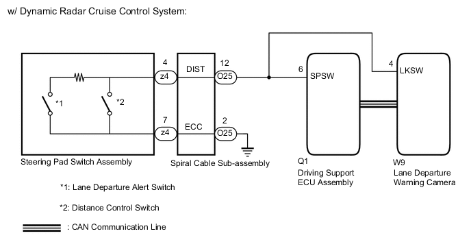
w/ Dynamic Radar Cruise Control System:
-
The lane departure warning camera receives a lane departure alert main switch signal from the steering pad switch assembly.
w/o Dynamic Radar Cruise Control System:
WIRING DIAGRAM
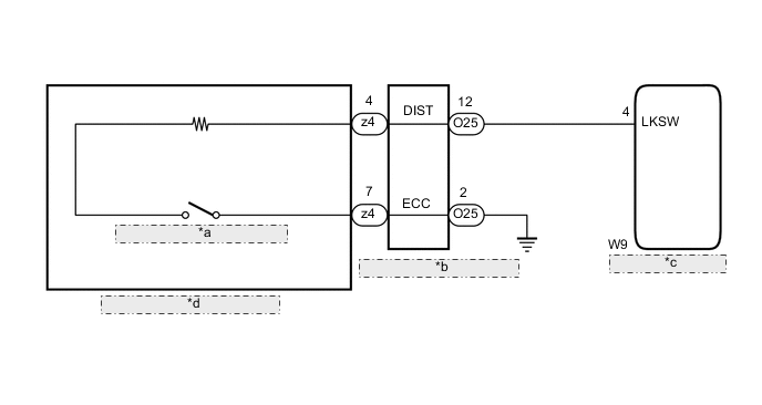
| *a | Lane Departure Alert Switch |
| *b | Spiral Cable Sub-assembly |
| *c | Lane Departure Warning Camera |
| *d | Steering Pad Switch Assembly |
CAUTION / NOTICE / HINT
Note
The vehicle is equipped with a Supplemental Restraint System (SRS) which includes components such as airbags. Before servicing (including removal or installation of parts), be sure to read the precaution for Supplemental Restraint System.
PROCEDURE
-
SYSTEM CHECK
-
Confirm the vehicle specification.
Result Result Proceed to w/ Dynamic Radar Cruise Control System A w/o Dynamic Radar Cruise Control System B
B 
INSPECT STEERING PAD SWITCH ASSEMBLY Click here
A 
-
-
INSPECT STEERING PAD SWITCH ASSEMBLY
-
Remove the steering pad switch assembly.
-
Inspect the steering pad switch assembly.
Result Proceed to OK NG
NG 
REPLACE STEERING PAD SWITCH ASSEMBLY Click here
OK
-
-
INSPECT SPIRAL CABLE SUB-ASSEMBLY
-
Remove the spiral cable sub-assembly.
-
Inspect the spiral cable sub-assembly.
Result Proceed to OK NG
NG
REPLACE SPIRAL CABLE SUB-ASSEMBLY Click here
OK
-
-
CHECK HARNESS AND CONNECTOR (SPIRAL CABLE SUB-ASSEMBLY - DRIVING SUPPORT ECU ASSEMBLY)
-
Disconnect the O25 spiral cable sub-assembly connector.
-
Disconnect the Q1 driving support ECU assembly connector.
-
Disconnect the W9 lane departure warning camera connector.
-
Measure the resistance according to the value(s) in the table below.
Standard Resistance Tester Connection Condition Specified Condition O25-12 (DIST) - Q1-6 (SPSW) Always Below 1 Ω O25-2 (ECC) - Body ground Always Below 1 Ω O25-12 (DIST), Q1-6 (SPSW) or W9-4 (LKSW) - Body ground Always 10 kΩ or higher Result Proceed to OK NG
NG
REPAIR OR REPLACE HARNESS OR CONNECTOR
OK
-
-
REPLACE DRIVING SUPPORT ECU ASSEMBLY
-
Replace the driving support ECU assembly with a new one.
Note
When replacing the driving support ECU assembly, always replace it with a new one. If a driving support ECU assembly which was installed to another vehicle is used, the information stored in the driving support ECU assembly will not match the information from the vehicle. As a result, a DTC may be stored.
Result Proceed to NEXT
NEXT
-
-
CHECK LANE DEPARTURE ALERT SYSTEM (LANE DEPARTURE ALERT INDICATOR)
-
Check that the lane departure alert indicator in the combination meter assembly illuminates when the lane departure alert system is turned on using the lane departure alert main switch.
Result Result Proceed to The lane departure alert indicator in the combination meter assembly illuminates when the lane departure alert system is turned on using the lane departure alert main switch A The lane departure alert indicator in the combination meter assembly does not illuminate when the lane departure alert system is turned on using the lane departure alert main switch B
A
PROCEED TO NEXT SUSPECTED AREA SHOWN IN PROBLEM SYMPTOMS TABLE Click here
B
END (DRIVING SUPPORT ECU ASSEMBLY WAS DEFECTIVE)
-
-
INSPECT STEERING PAD SWITCH ASSEMBLY
-
Remove the steering pad switch assembly.
-
Inspect the steering pad switch assembly.
Result Proceed to OK NG
NG
REPLACE STEERING PAD SWITCH ASSEMBLY Click here
OK
-
-
INSPECT SPIRAL CABLE SUB-ASSEMBLY
-
Remove the spiral cable sub-assembly.
-
Inspect the spiral cable sub-assembly.
Result Proceed to OK NG
NG
REPLACE SPIRAL CABLE SUB-ASSEMBLY Click here
OK
-
-
CHECK HARNESS AND CONNECTOR (SPIRAL CABLE SUB-ASSEMBLY - LANE DEPARTURE WARNING CAMERA)
-
Disconnect the O25 spiral cable sub-assembly connector.
-
Disconnect the W9 lane departure warning camera connector.
-
Measure the resistance according to the value(s) in the table below.
Standard Resistance Tester Connection Condition Specified Condition O25-12 (DIST) - W9-4 (LKSW) Always Below 1 Ω O25-2 (ECC) - Body ground Always Below 1 Ω O25-12 (DIST) or W9-4 (LKSW) - Body ground Always 10 kΩ or higher Result Proceed to OK NG
OK
PROCEED TO NEXT SUSPECTED AREA SHOWN IN PROBLEM SYMPTOMS TABLE Click here
NG
REPAIR OR REPLACE HARNESS OR CONNECTOR
-