ENGINE UNIT INSTALLATION

CAUTION / NOTICE / HINT
PROCEDURE
-
INSTALL WATER OUTLET SUB-ASSEMBLY
-
INSTALL ENGINE COOLANT TEMPERATURE SENSOR
-
INSTALL FUEL INJECTOR SEAL
-
INSTALL FUEL INJECTOR SET
-
INSTALL FUEL DELIVERY PIPE SUB-ASSEMBLY
-
INSTALL FUEL INJECTOR ASSEMBLY
-
INSTALL FUEL DELIVERY PIPE
-
SET FUEL PUMP WITH SEAL SUB-ASSEMBLY
-
TEMPORARILY INSTALL NO. 1 FUEL PIPE SUB-ASSEMBLY
-
INSTALL FUEL PUMP WITH SEAL SUB-ASSEMBLY
-
INSTALL NO. 1 FUEL PIPE SUB-ASSEMBLY
-
INSTALL NO. 1 FUEL PIPE
-
INSTALL WATER INLET HOUSING
Note
If a stud bolt is deformed or its threads are damaged, replace it.
-
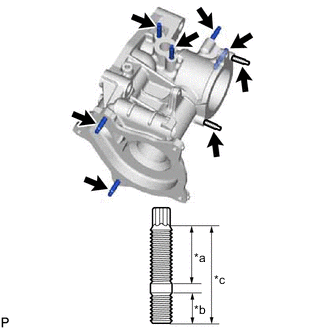
*a 16 mm (0.63 in.) *b 9.0 mm (0.354 in.) *c 27 mm (1.06 in.) Using an E6 "TORX" socket wrench, install the 8 stud bolts to the water inlet housing.
- Torque:
- 4.0 N*m { 41 kgf*cm, 35 in.*lbf }
-
Install a new gasket to the water inlet housing.
-
Install the water inlet housing to the cylinder block sub-assembly with the 2 bolts and nut.
- Torque:
- 43 N*m { 438 kgf*cm, 32 ft.*lbf }
Note
Keep the contact surfaces of the cylinder block sub-assembly and water inlet housing free of foreign matter.
Tech Tips
Align the straight pin of the cylinder block sub-assembly with the straight pin hole of the water inlet housing.
-
-
INSTALL NO. 5 WATER BY-PASS PIPE
-
Install a new gasket to the water inlet housing.
-
Install the No. 5 water by-pass pipe to the water inlet housing with the bolt and 2 nuts.
- Torque:
- 10 N*m { 102 kgf*cm, 7 ft.*lbf }
-
Connect the No. 11 water by-pass hose to the water outlet sub-assembly and slide the clip to secure it.
-
-
INSTALL WATER INLET WITH THERMOSTAT SUB-ASSEMBLY
-
INSTALL ENGINE WATER PUMP ASSEMBLY
-
INSTALL WIRE HARNESS CLAMP BRACKET
-
Install the 7 wire harness clamp brackets with the 9 bolts.
- Torque:
- 10 N*m { 102 kgf*cm, 7 ft.*lbf }
-
-
INSTALL ENGINE COVER JOINT
-
Install the 3 engine cover joints to the cylinder head cover sub-assembly.
- Torque:
- 10 N*m { 102 kgf*cm, 7 ft.*lbf }
-
-
INSTALL IGNITION COIL ASSEMBLY
-
INSTALL FRONT NO. 1 ENGINE MOUNTING BRACKET LH
-
Install the front No. 1 engine mounting bracket LH to the cylinder block sub-assembly with the 4 bolts.
- Torque:
- 43 N*m { 438 kgf*cm, 32 ft.*lbf }
-
-
INSTALL FRONT NO. 1 ENGINE MOUNTING BRACKET RH
-
Install the front No. 1 engine mounting bracket RH to the cylinder block sub-assembly with the 4 bolts.
- Torque:
- 43 N*m { 438 kgf*cm, 32 ft.*lbf }
-
-
INSTALL NO. 3 WATER BY-PASS PIPE
-
Install the No. 3 water by-pass pipe to the cylinder block sub-assembly with the 3 bolts.
- Torque:
- 21 N*m { 214 kgf*cm, 15 ft.*lbf }
-
Connect the No. 13 water by-pass hose to the water outlet sub-assembly and slide the clip to secure it.
-
-
INSTALL NO. 2 WATER BY-PASS PIPE
-
Install the No. 2 water by-pass pipe to the cylinder head sub-assembly with the 2 bolts.
- Torque:
- 10 N*m { 102 kgf*cm, 7 ft.*lbf }
-
-
INSTALL EGR COOLER ASSEMBLY
-
INSTALL EGR VALVE BRACKET
-
INSTALL NO. 1 WATER BY-PASS PIPE
-
Install a new gasket and the No. 1 water by-pass pipe with the bolt and 2 nuts.
- Torque:
- 10 N*m { 102 kgf*cm, 7 ft.*lbf }
-
Connect the water by-pass hose to the No. 2 water by-pass pipe and slide the clip to secure it.
-
-
INSTALL NO. 1 COMPRESSOR MOUNTING BRACKET
-
Install the No. 1 compressor mounting bracket with the 5 bolts.
- Torque:
- 24.5 N*m { 250 kgf*cm, 18 ft.*lbf }
-