FRAME WIRE INSTALLATION
PROCEDURE
-
INSTALL FRAME WIRE
CAUTION:
Wear insulated gloves.
-
Install the frame wire with 2 new clamps.
Note
The clamps are non-reusable parts.
-
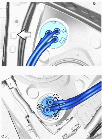

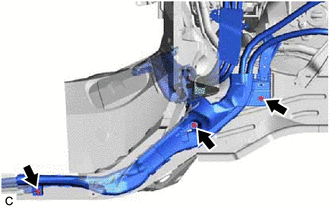
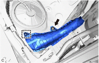
Front Side Insert the frame wire into the floor panel hole and engage the 3 claws.
Tech Tips
The arrow should be pointing toward the front of the vehicle.
-
Install the bolt.
- Torque:
- 13 N*m { 133 kgf*cm, 10 ft.*lbf }
-
Engage the clamp.
-
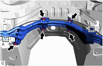
for LHD:
-
Engage the clamp (B).
-
Install the 5 nuts.
- Torque:
- 8.0 N*m { 82 kgf*cm, 71 in.*lbf }
-
Engage the clamp (A).
-
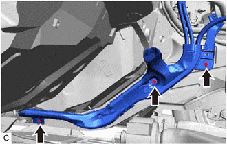
Install the 3 bolts.
- Torque:
- 13 N*m { 133 kgf*cm, 10 ft.*lbf }
-
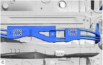
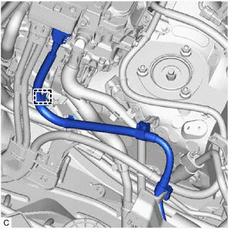
Engage the 2 clamps and install the wiring harness protector to the frame wire.
-
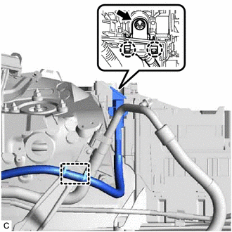
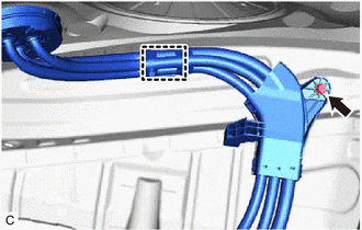
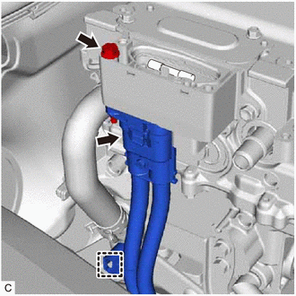
Engage the 2 claws to connect the frame wire to the engine room relay block and junction block assembly.
-
Install the nut.
- Torque:
- 10.5 N*m { 107 kgf*cm, 8 ft.*lbf }
-
Engage the clamp.
-
Remove the connector cover assembly.
-
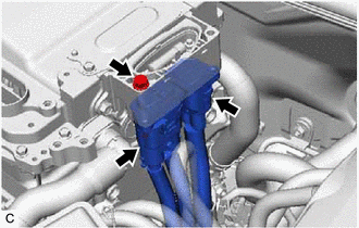
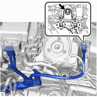
Connect the 2 frame wire connectors to the inverter with converter assembly with the bolt.
- Torque:
- 8.0 N*m { 82 kgf*cm, 71 in.*lbf }
Note
-
Do not allow any foreign matter or water to enter the inverter with converter assembly.
-
Do not touch the waterproof seal or terminals of the connector.
-
Do not damage the terminals, connector housing or inverter with converter assembly during disconnection.
-
Make sure that the connectors are fully engaged.
-
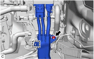
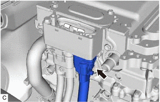
Engage the clamp.
-
Install the nut.
- Torque:
- 8.0 N*m { 82 kgf*cm, 71 in.*lbf }
-
Install the connector cover assembly.
-
-
for RHD:
-
Install the 3 bolts.
- Torque:
- 13 N*m { 133 kgf*cm, 10 ft.*lbf }
-
Engage the 2 clamps and install the wiring harness protector to the frame wire.
-
Remove the connector cover assembly.
-
Connect the frame wire connector to the inverter with converter assembly with the bolt.
- Torque:
- 8.0 N*m { 82 kgf*cm, 71 in.*lbf }
Note
-
Do not allow any foreign matter or water to enter the inverter with converter assembly.
-
Do not touch the waterproof seal or terminals of the connector.
-
Do not damage the terminals, connector housing or inverter with converter assembly during disconnection.
-
Make sure that the connectors are fully engaged.
-
Engage the clamp.
-
Engage the 2 claws to connect the frame wire to the engine room relay block and junction block assembly.
-
Install the nut.
- Torque:
- 10.5 N*m { 107 kgf*cm, 8 ft.*lbf }
-
Engage the clamp.
-
Connect the air conditioner harness connector to the inverter with converter assembly.
Note
-
Do not allow any foreign matter or water to enter the inverter with converter assembly.
-
Do not touch the waterproof seal or terminals of the connector.
-
Do not damage the terminals, connector housing or inverter with converter assembly during disconnection.
-
Make sure that the connectors are fully engaged.
-
-
Engage the clamp.
-
Install the connector cover assembly.
-
-
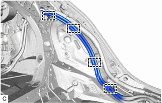
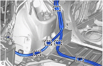
Engage the 4 clamps.
-
Engage the clamp to install the wiring harness protector.
-
Install the nut.
- Torque:
- 5.5 N*m { 56 kgf*cm, 49 in.*lbf }
-
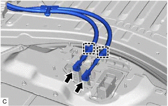
Connect the 2 frame wire connectors to the hybrid battery terminal block.
Note
The connectors should be connected securely.
-
Engage the 2 clamps to the upper hybrid battery cover sub-assembly.
-
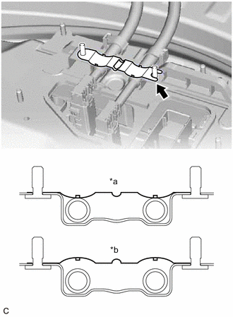
*a Correct *b Incorrect Install the earth terminal to the upper hybrid battery cover sub-assembly.
Note
Be sure to face the correct side of the earth terminal up.
Tech Tips
The left side and right side can be reversed when installing the earth terminal.
-
Engage the 5 clamps.
-
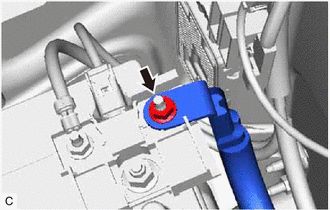
Connect the frame wire to the fusible link block assembly with the nut.
- Torque:
- 6.5 N*m { 66 kgf*cm, 58 in.*lbf }
-
Install the battery terminal connector cover.
-
-
INSTALL NO. 4 HV BATTERY SHIELD PANEL
-
INSTALL FRONT QUARTER TRIM PANEL ASSEMBLY LH
-
INSTALL FRONT DOOR SCUFF PLATE LH
-
INSTALL LUGGAGE COMPARTMENT TRIM COVER LH (for LH Side)
-
INSTALL ROPE HOOK ASSEMBLY (for LH Side)
-
INSTALL FRONT UPPER LUGGAGE COMPARTMENT TRIM COVER
-
INSTALL NO. 1 LUGGAGE COMPARTMENT LAMP ASSEMBLY
-
INSTALL NO. 2 ROOM PARTITION COVER
-
INSTALL REAR SEAT SUB FLOOR PANEL
-
INSTALL REAR LUGGAGE COMPARTMENT TRIM COVER
-
INSTALL FRONT LUGGAGE COMPARTMENT TRIM COVER
-
INSTALL REAR SEAT ASSEMBLY LH
-
INSTALL FRONT FLOOR COVER LH
-
Engage the 6 clips to install the front floor cover LH.
-
-
INSTALL FRONT NO. 4 FLOOR HEAT INSULATOR
-
Install the front No. 4 floor heat insulator with the 2 bolts.
- Torque:
- 4.9 N*m { 50 kgf*cm, 43 in.*lbf }
-
-
INSTALL FRONT NO. 6 FLOOR HEAT INSULATOR
-
Install the front No. 6 floor heat insulator with the 3 nuts.
- Torque:
- 5.4 N*m { 55 kgf*cm, 48 in.*lbf }
-
-
INSTALL FUEL TANK ASSEMBLY
-
INSTALL ENGINE ASSEMBLY WITH TRANSMISSION