HV BATTERY INSTALLATION

PROCEDURE
-
INSTALL UPPER NO. 3 HV BATTERY CARRIER BRACKET
CAUTION:
Wear insulated gloves.
-
Install the upper No. 3 HV battery carrier bracket to the HV battery with the 2 nuts.
- Torque:
- 7.5 N*m { 76 kgf*cm, 66 in.*lbf }
-
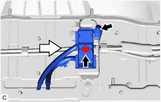
Install the EV battery plug to the upper No. 3 HV battery carrier bracket with the bolt as shown in the illustration.
- Torque:
- 7.5 N*m { 76 kgf*cm, 66 in.*lbf }
-
Connect the EV battery plug connector.
Note
The connector should be connected securely.
-
-
INSTALL UPPER NO. 6 HV BATTERY CARRIER BRACKET
CAUTION:
Wear insulated gloves.
-
Install the upper No. 6 HV battery carrier bracket to the HV battery with the 4 nuts.
- Torque:
- 7.5 N*m { 76 kgf*cm, 66 in.*lbf }
-
-
INSTALL HV BATTERY JUNCTION BLOCK ASSEMBLY
-
INSTALL UPPER NO. 5 HV BATTERY CARRIER BRACKET
CAUTION:
Wear insulated gloves.
-
Install the upper No. 5 HV battery carrier bracket to the HV battery with the 4 nuts.
- Torque:
- 7.5 N*m { 76 kgf*cm, 66 in.*lbf }
-
-
INSTALL BATTERY VOLTAGE SENSOR
-
INSTALL UPPER NO. 1 HYBRID BATTERY COVER SUB-ASSEMBLY
CAUTION:
Wear insulated gloves.
-
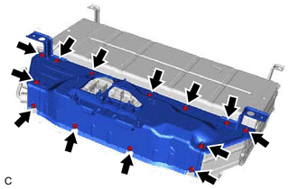
Install the upper No. 1 hybrid battery cover sub-assembly to the HV battery with the 13 nuts.
- Torque:
- 7.5 N*m { 76 kgf*cm, 66 in.*lbf }
-
-
INSTALL HV BATTERY
CAUTION:
Wear insulated gloves.
-
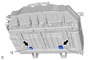
*1 Front Hybrid Battery Guide (Yellow) *2 Rear Hybrid Battery Guide (White) Install the front hybrid battery guide and rear hybrid battery guide to the HV battery.
-
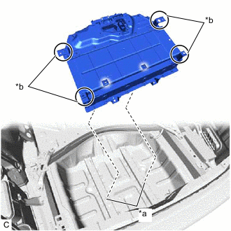
*a Guide Pin *b Areas to be Held Hold the HV battery at the areas shown in the illustration and insert the guide pins into the front hybrid battery guide and rear hybrid battery guide to temporarily install the HV battery to the vehicle.
Note
-
To prevent the wire harness from being caught, make sure to bundle the wire harness using insulating tape or equivalent.
-
Use cardboard or other similar material to protect the HV battery and vehicle body from damage.
-
Since the HV battery is very heavy, 2 people are needed to install the HV battery. When installing the HV battery, do not damage the parts around it.
-
When removing/installing/moving the HV battery, make sure not to tilt it more than 80°.
-
While lowering the HV battery to the vehicle, do not allow it to contact the vehicle.
-
When moving the HV battery, make sure to use an engine lifter.
Tech Tips
Attach tape to the feet and edges of the HV battery to protect tools and the vehicle body.
-
-
Install the HV battery with the 2 bolts.
- Torque:
- 20 N*m { 204 kgf*cm, 15 ft.*lbf }
-
Connect the HV battery connector.
Note
The connector should be connected securely.
-
Install the 4 bolts.
- Torque:
- 40 N*m { 408 kgf*cm, 30 ft.*lbf }
-
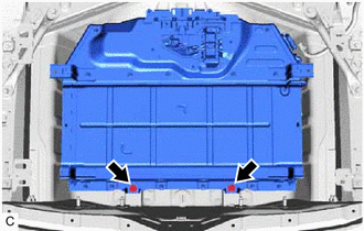
Install the 2 battery drain plugs as indicated by the arrows, in the order shown in the illustration.
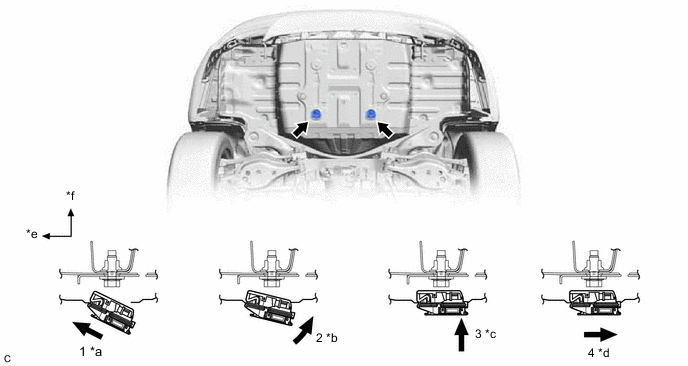
*a Engage the front claw to the vehicle. *b While pushing the battery drain plug toward the front of the vehicle, engage the rear claw. *c Push the battery drain plug upward. *d Securely install the battery drain plug by pushing it toward the rear side of the vehicle. *e Front Side *f Upper Side Note
-
If a claw or the waterproofing rubber is damaged, replace the battery drain plug with a new one.
-
If the drain valve is clogged, replace the battery drain plug with a new one.
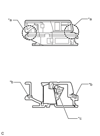
*a Claw *b Waterproofing Rubber *c Drain Valve -
-
Install the 2 grommets.
-
-
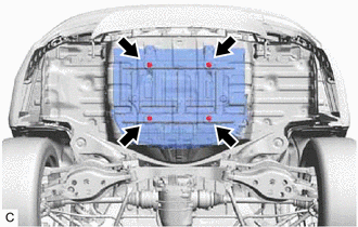
INSTALL NO. 1 FLOOR UNDER COVER ASSEMBLY
-
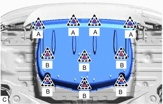
Engage the 6 clips (B) to install the No. 1 floor under cover assembly.
-
Install the 4 clips (A).
-
-
INSTALL NO. 3 HYBRID BATTERY INTAKE DUCT
-
Install the No. 3 hybrid battery intake duct to the No. 4 hybrid battery intake duct.
-
-
INSTALL NO. 4 HYBRID BATTERY INTAKE DUCT
CAUTION:
Wear insulated gloves.
-
Install the No. 4 hybrid battery intake duct with No. 3 hybrid battery intake duct to the HV battery with the 2 clips.
-
-
INSTALL NO. 3 HYBRID BATTERY INTAKE DUCT
-
CONNECT FRAME WIRE
CAUTION:
Wear insulated gloves.
-
Connect the 2 frame wire connectors to the hybrid battery terminal block.
Note
The connectors should be connected securely.
-
Engage the 2 clamps.
-
Install the earth terminal to the upper No. 1 hybrid battery cover sub-assembly.
Note
Be sure to face the correct side of the earth terminal up.
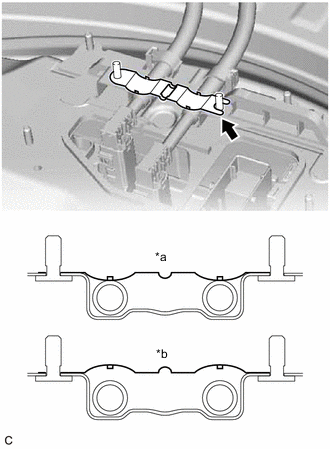
*a Correct *b Incorrect Tech Tips
The left side and right side can be reversed when installing the earth terminal.
-
-
INSTALL NO. 4 HV BATTERY SHIELD PANEL
CAUTION:
Wear insulated gloves.
-
Install the No. 4 HV battery shield panel to the upper No. 1 hybrid battery cover sub-assembly with the 4 nuts.
- Torque:
- 7.5 N*m { 76 kgf*cm, 66 in.*lbf }
-
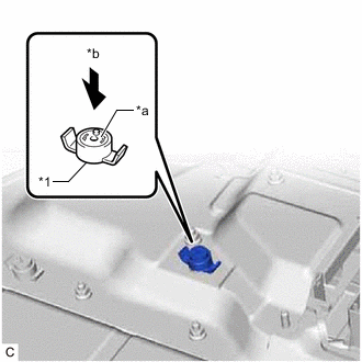
*1 Battery Cover Lock Striker *a Button *b Push Install the battery cover lock striker, then push the button to lock it.
-
-
INSTALL REAR NO. 1 FLOOR CROSSMEMBER BRACE LH
-
Install the rear No. 1 floor crossmember brace LH with the 2 bolts and 2 nuts.
- Torque:
- 50 N*m { 510 kgf*cm, 37 ft.*lbf }
-
Engage the clamp to the rear No. 1 floor crossmember brace LH.
-
-
INSTALL REAR NO. 1 FLOOR CROSSMEMBER BRACE RH
-
Install the rear No. 1 floor crossmember brace RH with the 2 bolts and 2 nuts.
- Torque:
- 50 N*m { 510 kgf*cm, 37 ft.*lbf }
-
-
INSTALL LUGGAGE COMPARTMENT TRIM COVER RH (for RH Side)
-
INSTALL ROPE HOOK ASSEMBLY (for RH Side)
-
INSTALL LUGGAGE COMPARTMENT TRIM COVER LH (for LH Side)
-
INSTALL ROPE HOOK ASSEMBLY (for LH Side)
-
INSTALL FRONT UPPER LUGGAGE COMPARTMENT TRIM COVER
-
INSTALL NO. 1 LUGGAGE COMPARTMENT LIGHT ASSEMBLY
-
INSTALL NO. 2 ROOM PARTITION COVER
-
INSTALL NO. 1 ROOM PARTITION COVER
-
INSTALL REAR SEAT SUB FLOOR PANEL
-
INSTALL REAR SEAT ASSEMBLY
-
INSTALL REAR LUGGAGE COMPARTMENT TRIM COVER
-
INSTALL FRONT LUGGAGE COMPARTMENT TRIM COVER
-
INSTALL SERVICE PLUG GRIP