INVERTER WITH CONVERTER INSTALLATION
PROCEDURE
-
INSTALL NO. 5 INVERTER BRACKET
Tech Tips
Perform this procedure only when replacement of the No. 5 inverter bracket is necessary.
-
Temporarily install the No. 5 inverter bracket with the 3 bolts.
-
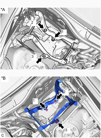
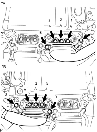
*A for LHD *B for RHD Tighten the 3 bolts in the order shown in the illustration.
- Torque:
- 8.0 N*m { 82 kgf*cm, 71 in.*lbf }
-
Install the power steering ECU assembly (for LHD).
-
Install the power steering ECU assembly (for RHD).
-
-
INSTALL NO. 1 INVERTER COOLING HOSE
Tech Tips
Perform this procedure only when replacement of the No. 1 inverter cooling hose is necessary.
-
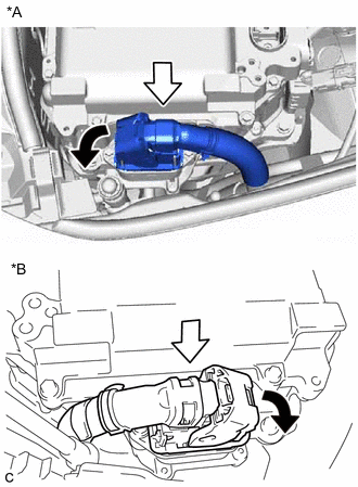
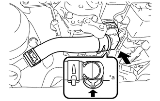
Install the No. 1 inverter cooling hose to the inverter with converter assembly and slide the 2 clips to secure it.
Note
Do not remove the pieces of cloth or plastic bags from the pipes until installation.
Tech Tips
Make sure that the clips are positioned as shown in the illustration.
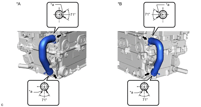
*A for LHD *B for RHD *a Alignment Mark - -
-
-
INSTALL HIGH VOLTAGE FUSE
CAUTION:
Wear insulated gloves.
Tech Tips
Perform this procedure only when replacement of the high voltage fuse is necessary.
-
Remove the connector cover assembly.
-
Install the high voltage fuse with the 2 new nuts.
- Torque:
- 4.0 N*m { 41 kgf*cm, 35 in.*lbf }
Note
Be sure to use a torque wrench to tighten the nuts.
-
Temporarily install the connector cover assembly.
-
-
INSTALL INVERTER BUS-BAR PLATE SUB-ASSEMBLY
-
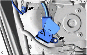
Align the inverter bus-bar plate sub-assembly with the stoppers, guide bar, stud bolt and guide pin of the inverter with converter assembly, and temporarily install the inverter bus-bar plate sub-assembly to the inverter with converter assembly.
Note
If the inverter bus-bar plate sub-assembly is dropped or deformed, replace it with a new one.
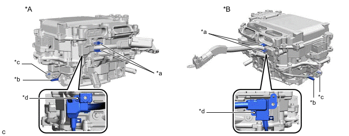
*A for LHD *B for RHD *a Stopper *b Guide Bar *c Stud Bolt *d Guide Pin -
Temporarily install the nut to the inverter bus-bar plate sub-assembly.
Note
To prevent the threads from being damaged, make sure to perform this step by hand.
-
Install the bolt.
- Torque:
- 8.0 N*m { 82 kgf*cm, 71 in.*lbf }
-
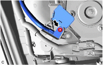
Engage the 2 clamps to the inverter bus-bar plate sub-assembly.
-
Tighten the nut.
- Torque:
- 18 N*m { 184 kgf*cm, 13 ft.*lbf }
-
Close the terminal cover.
-
-
INSTALL WIRING HARNESS CLAMP BRACKET (for RHD)
-
Install the wiring harness clamp bracket to the inverter with converter assembly with the bolt.
- Torque:
- 10 N*m { 102 kgf*cm, 7 ft.*lbf }
-
-
INSTALL NO. 4 INVERTER BRACKET
-
Install the No. 4 inverter bracket to the inverter with converter assembly with the 2 bolts.
- Torque:
- 8.0 N*m { 82 kgf*cm, 71 in.*lbf }
-
-
INSTALL INVERTER WITH CONVERTER ASSEMBLY
CAUTION:
Wear insulated gloves.
-
Temporarily install the inverter with converter assembly with the 4 bolts.
Note
-
Since the inverter with converter assembly is very heavy, 2 people are needed to install the inverter with converter assembly. When installing the inverter with converter assembly, do not damage the parts around it.
-
To prevent damage, do not hold the inverter with converter assembly by the connectors.
-
To prevent damage due to static electricity, do not touch the terminals of the disconnected connectors.
-
-
Tighten the 4 bolts in the order shown in the illustration.
- Torque:
- 8.0 N*m { 82 kgf*cm, 71 in.*lbf }
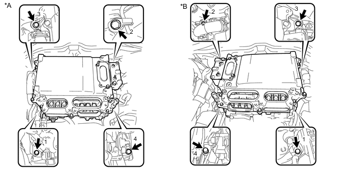
*A for LHD *B for RHD -
*A for LHD *B for RHD Connect the inverter with converter assembly connector to the inverter with converter assembly and lock the connector with the lock lever as shown in the illustration.
-
for LHD:
-
Connect the inverter with converter assembly connector.
-
Connect the inverter bus-bar plate sub-assembly with the nut.
- Torque:
- 6.9 N*m { 70 kgf*cm, 61 in.*lbf }
-
Connect the engine room main wire to the inverter bus-bar plate sub-assembly with the nut.
- Torque:
- 10.5 N*m { 107 kgf*cm, 8 ft.*lbf }
-
Close the inverter bus-bar plate sub-assembly cover.
-
-
for RHD:
-
Engage the wiring harness clamp.
-
Connect the inverter with converter assembly connector and engage the clamp.
Tech Tips
If the clamp is damaged when disconnecting it, it is not necessary to reconnect it to the vehicle body.
-
Engage the 2 claws to connect the inverter bus-bar plate sub-assembly to the engine room relay block and junction block assembly.
-
Install the nut to the inverter bus-bar plate sub-assembly.
- Torque:
- 10.5 N*m { 107 kgf*cm, 8 ft.*lbf }
-
Install the No. 1 relay block cover to the engine room relay block and junction block assembly.
-
-
-
INSTALL NO. 6 INVERTER BRACKET
-
Install the No. 6 inverter bracket with the 2 bolts.
- Torque:
- 8.0 N*m { 82 kgf*cm, 71 in.*lbf }
-
-
REMOVE CONNECTOR COVER ASSEMBLY
-
CONNECT FRAME WIRE
CAUTION:
Wear insulated gloves.
-
for LHD:
-
Connect the 2 frame wire connectors to the inverter with converter assembly with the bolt.
- Torque:
- 8.0 N*m { 82 kgf*cm, 71 in.*lbf }
Note
-
Do not allow any foreign matter or water to enter the inverter with converter assembly.
-
Do not touch the connector waterproofing rubber or terminals.
-
Do not damage the connectors, connector housings or inverter with converter assembly during connection.
-
Make sure that the connector is fully engaged.
-
-
for RHD:
-
Connect the frame wire connector to the inverter with converter assembly with the bolt.
- Torque:
- 8.0 N*m { 82 kgf*cm, 71 in.*lbf }
Note
-
Do not allow any foreign matter or water to enter the inverter with converter assembly.
-
Do not touch the connector waterproofing rubber or terminals.
-
Do not damage the connector, connector housing or inverter with converter assembly during connection.
-
Make sure that the connector is fully engaged.
-
Engage the clamp.
-
-
-
CONNECT AIR CONDITIONING HARNESS (for RHD)
CAUTION:
Wear insulated gloves.
-
Connect the air conditioning harness connector to the inverter with converter assembly.
Note
-
Do not allow any foreign matter or water to enter the inverter with converter assembly.
-
Do not touch the connector waterproofing rubber or terminals.
-
Do not damage the connector, connector housing or inverter with converter assembly during connection.
-
Make sure that the connector is fully engaged.
-
-
-
INSTALL CONNECTOR COVER ASSEMBLY
CAUTION:
Wear insulated gloves.
-
Install the connector cover assembly to the inverter with converter assembly with the 2 bolts.
- Torque:
- 8.0 N*m { 82 kgf*cm, 71 in.*lbf }
Note
-
Visually confirm that the connector cover assembly waterproofing rubber is securely installed before installing the connector cover assembly.
-
Do not touch the connector cover assembly waterproofing rubber.
-
Make sure that the interlock is fully engaged.
-
-
CONNECT INLET NO. 1 INVERTER COOLING HOSE (for LHD)
-
*a Up *b Left Side Connect the inlet No. 1 inverter cooling hose to the inverter with converter assembly and slide the clip to secure it.
Note
Do not remove the pieces of cloth or plastic bags from the pipe and disconnected hose until installation.
Tech Tips
Make sure that the clip is positioned as shown in the illustration.
-
-
CONNECT OUTLET NO. 1 INVERTER COOLING HOSE (for LHD)
-
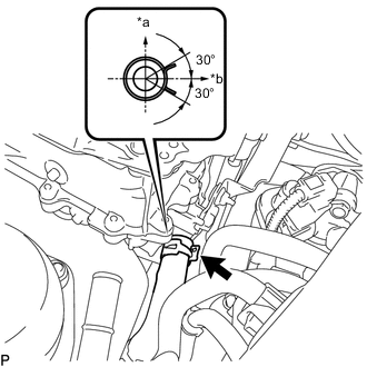
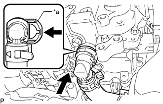
*a Retainer Connect the outlet No. 1 inverter cooling hose to the inverter with converter assembly and lock the hose with the retainer as shown in the illustration.
Note
-
Push in the retainer until a click sound is heard.
-
Pull on the hose to confirm that the hose is securely connected.
-
If there is foreign matter on the union or the O-ring, clean it with water and finger scouring.
-
To prevent foreign matter from entering the cooling system, do not remove the pieces of cloth or plastic bags from the pipe and disconnected hose until installation.
-
-
-
CONNECT INLET NO. 2 INVERTER COOLING HOSE (for RHD)
-
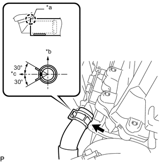
*a Insert *b Up *c Right Side Connect the inlet No. 2 inverter cooling hose to the inverter with converter assembly and slide the clamp to secure it.
Note
Do not remove the pieces of cloth or plastic bags from the pipe and disconnected hose until installation.
Tech Tips
-
Insert the hose as shown in the illustration.
-
Make sure that the clamp is positioned as shown in the illustration.
-
-
-
CONNECT OUTLET NO. 2 INVERTER COOLING HOSE (for RHD)
-
*a Retainer Connect the outlet No. 2 inverter cooling hose to the inverter with converter assembly and lock the hose with the retainer as shown in the illustration.
Note
-
Push in the retainer until a click sound is heard.
-
Pull on the hose to confirm that the hose is securely connected.
-
If there is foreign matter on the union or the O-ring, clean it with water and finger scouring.
-
To prevent foreign matter from entering the cooling system, do not remove the pieces of cloth or plastic bags from the pipe and disconnected hose until installation.
-
-
-
INSTALL INLET INVERTER COOLING PIPE (for RHD)
-
Install the inlet inverter cooling pipe with the bolt and nut.
- Torque:
- 12.5 N*m { 127 kgf*cm, 9 ft.*lbf }
-
-
CONNECT AIR CONDITIONING HARNESS (for RHD)
-
Engage the 3 clamps.
-
-
CONNECT GENERATOR CABLE
CAUTION:
Wear insulated gloves.
-
Temporarily install the generator cable to the inverter with converter assembly with the 5 bolts.
Note
-
Do not allow any foreign matter or water to enter the inverter with converter assembly.
-
Do not touch the connector waterproofing rubber or terminals.
-
Do not damage the terminals, connector housings or inverter with converter assembly when connecting them.
-
-
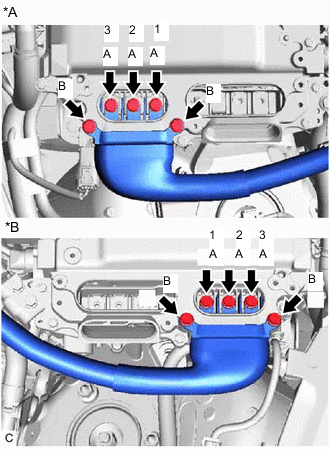
*A for LHD *B for RHD Using an insulated tool, fully tighten the 3 bolts (A) in the order shown in the illustration.
- Torque:
- 8.0 N*m { 82 kgf*cm, 71 in.*lbf }
-
Using an insulated tool, fully tighten the 2 bolts (B).
- Torque:
- 8.0 N*m { 82 kgf*cm, 71 in.*lbf }
-
-
CONNECT MOTOR CABLE
CAUTION:
Wear insulated gloves.
-
Temporarily install the motor cable to the inverter with converter assembly with the 5 bolts.
Note
-
Do not allow any foreign matter or water to enter the inverter with converter assembly.
-
Do not touch the connector waterproofing rubber or terminals.
-
Do not damage the terminals, connector housings or inverter with converter assembly when connecting them.
-
-
*A for LHD *B for RHD Using an insulated tool, fully tighten the 3 bolts (A) in the order shown in the illustration.
- Torque:
- 8.0 N*m { 82 kgf*cm, 71 in.*lbf }
-
Using an insulated tool, fully tighten the 2 bolts (B).
- Torque:
- 8.0 N*m { 82 kgf*cm, 71 in.*lbf }
-
-
INSTALL INVERTER TERMINAL COVER
CAUTION:
Wear insulated gloves.
-
Temporarily install the inverter terminal cover to the inverter with converter assembly.
Note
-
Do not touch the inverter terminal cover waterproofing rubber.
-
Do not allow any foreign matter or water to enter the inverter with converter assembly.
-
Make sure that the interlock is fully engaged.
-
-
Press the inverter terminal cover by hand until it is firmly attached to the inverter with converter assembly.
-
Install the 3 bolts.
- Torque:
- 8.0 N*m { 82 kgf*cm, 71 in.*lbf }
-
-
INSTALL INVERTER MOTOR CABLE BRACKET ASSEMBLY
-
Install the inverter motor cable bracket assembly to the inverter with converter assembly with the 2 bolts.
- Torque:
- 8.0 N*m { 82 kgf*cm, 71 in.*lbf }
-
Engage the 2 clamps to the inverter motor cable bracket assembly.
-
-
CONNECT INVERTER COOLING HOSE (for RHD)
-
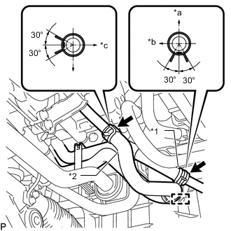
*1 No. 4 Inverter Cooling Hose *2 No. 5 Inverter Cooling Hose *a Upper Side *b Front Side *c Left Side Connect the No. 4 inverter cooling hose to the inlet inverter cooling pipe and slide the clip to secure it.
Note
Do not remove the pieces of cloth or plastic bags from the pipe and disconnected hose until installation.
Tech Tips
Make sure that the clip is positioned as shown in the illustration.
-
Connect the No. 5 inverter cooling hose to the inlet inverter cooling pipe and slide the clip to secure it.
Note
Do not remove the pieces of cloth or plastic bags from the pipe and disconnected hose until installation.
Tech Tips
Make sure that the clip is positioned as shown in the illustration.
-
Engage the clamp to the inlet inverter cooling pipe.
-
-
INSTALL SERVICE PLUG GRIP
-
ADD COOLANT (for Inverter)
-
INSPECT FOR COOLANT LEAK (for Inverter)
-
INSTALL NO. 1 ENGINE UNDER COVER ASSEMBLY