HYBRID CONTROL SYSTEM, Diagnostic DTC:P1C2D-587
| DTC Code | DTC Name |
|---|---|
| P1C2D-587 | Hybrid Battery Voltage / DC/DC Converter Voltage Correlation |
DTC SUMMARY
-
MALFUNCTION DESCRIPTION
The hybrid vehicle control ECU assembly detects a VB sensor or VL sensor malfunction.
The cause of this malfunction may be one of the following:
-
Voltage sensor malfunction
-
Motor generator control ECU (MG ECU) malfunction
-
Communication (wire harness) malfunction
Inside of inverter voltage sensor circuit malfunction
-
HV battery malfunction
-
HV battery junction block assembly malfunction
-
Inverter with converter assembly malfunction
-
High-voltage wire harness malfunction
-
High-voltage connector or connection malfunction
High voltage system malfunction
-
-
Inspection Overview
Inspection Content Reason (Narrow Down in Order Using Inspection Procedures Below) Inspection Step Check for DTCs (HV) Output DTCs 1 Check for DTCs (check voltage sensor malfunction locations)
Check for DTCs (drive test)
Put vehicle in ready ON (vehicle stopped or being driven) and then check whether DTCs are output again. 3, 4 Read value using GTS Data List value 5 Check freeze frame data (HV) FREEZE FRAME DATA 6, 7 Read value using GTS Accelerator and brake pedal simultaneously depressed Data List value 8
DESCRIPTION
For a description of the boost converter.
The MG ECU uses a voltage sensor (VL) that is built into the boost converter to detect the high voltage before it is boosted. The ECU also uses the battery voltage sensor to detect HV battery voltage (VB).
Tech Tips
Using the GTS, check the Data List values of "Power Resource VB" and "Batt Pack Current Val". If these values are not within the range below, there is a malfunction in the battery voltage sensor circuit.
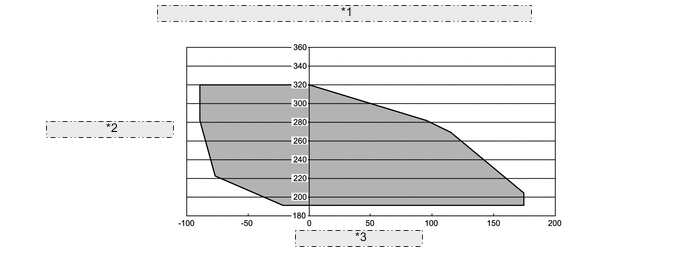
| *1 | HV Battery Voltage to HV Battery Current 20 to 40°C (68 to 104°F) |
| *2 | HV Battery Voltage (V) |
| *3 | HV Battery Current (A) |
| DTC No. | Detection Item | DTC Detection Condition | Trouble Area | MIL | Warning Indicate |
|---|---|---|---|---|---|
| P1C2D-587 | Hybrid Battery Voltage / DC/DC Converter Voltage Correlation | Voltages from HV battery voltage (VB) sensor and boost converter voltage (VL) sensor deviate: Difference between "VL-Voltage before Boosting" and "Power Resource VB" is large when the boosting request is given. (1 trip detection logic) |
|
Comes on | Master Warning Light: Comes on |
| DTC No. | Data List |
|---|---|
| P1C2D-587 |
|
CAUTION / NOTICE / HINT
Tech Tips
When the accelerator pedal is not depressed with the power switch on (READY) and the shift lever in P, if "VL-Voltage before Boosting" and the "Power Resource VB" is approximately same after repair, the condition is judged as normal.
PROCEDURE
-
CHECK DTC OUTPUT (HYBRID CONTROL)
-
Connect the GTS to the DLC3.
-
Turn the power switch on (IG).
-
Enter the following menus: Powertrain / Hybrid Control / Trouble Codes.
-
Check for DTCs.
Powertrain > Hybrid Control > Trouble CodesResult Result Proceed to
-
Only P1C2D-587 is output.
-
DTCs other than "P0CA3-442 and DTCs in Chart Below" are output at the same time.
One of the following applies:
A P1C2D and P0CA3-442 (voltage execution value malfunction) are output at the same time. B DTC indicated in Chart 1 is output at the same time. C DTC indicated in Chart 2 is output at the same time. D Table 1 Malfunction Content Relevant DTC Microcomputer malfunction P0A1A-151, 658 Generator Control Module P0A1B-786 Drive Motor "A" Control Module P0A1D-148 Hybrid Powertrain Control Module P1C2A-155 Generator A/D Converter Circuit P1CA6-156 Generator Control Module Malfunction P1CA7-193 Drive Motor Control Module Malfunction P2511-149 HV CPU Power Relay Sense Circuit Intermittent No Continuity P3133-659 Communication Error from Generator to Drive Motor "A" P3134-661 Communication Error from Drive Motor "A" to Generator P324E-788 MG-ECU Power Relay Intermittent Circuit Power source circuit malfunction P06E6-164 Sensor Power Supply "C" Circuit / Open P1C73-512 Sensor Standard Voltage "F" Circuit / Open Communication system malfunction U0110 (all INF codes)*1 Lost Communication with Drive Motor Control Module "A" Sensor and actuator circuit malfunction P0B23-129 Hybrid Battery "A" Voltage P0D2F-266 Drive Motor "A" Inverter Voltage Sensor Circuit Low P0D30-267 Drive Motor "A" Inverter Voltage Sensor Circuit High P0E32-585 DC/DC Converter Voltage Sensor "A" Range / Performance P0E33-589 DC/DC Converter Voltage Sensor "A" Low P0E34-590 DC/DC Converter Voltage Sensor "A" High System malfunction P3004-132 High Voltage Power Resource Table 2 Malfunction Content Relevant DTC Microcomputer malfunction P0AFC-123 Hybrid Battery Pack Sensor Module Sensor and actuator circuit malfunction P0B3D-123 Hybrid Battery Voltage Sensor "A" Circuit Low P0B42-123 Hybrid Battery Voltage Sensor "B" Circuit Low P0B47-123 Hybrid Battery Voltage Sensor "C" Circuit Low P0B4C-123 Hybrid Battery Voltage Sensor "D" Circuit Low P0B51-123 Hybrid Battery Voltage Sensor "E" Circuit Low P0B56-123 Hybrid Battery Voltage Sensor "F" Circuit Low P0B5B-123 Hybrid Battery Voltage Sensor "G" Circuit Low P0B60-123 Hybrid Battery Voltage Sensor "H" Circuit Low P0B65-123 Hybrid Battery Voltage Sensor "I" Circuit Low P0B6A-123 Hybrid Battery Voltage Sensor "J" Circuit Low P0B6F-123 Hybrid Battery Voltage Sensor "K" Circuit Low P0B74-123 Hybrid Battery Voltage Sensor "L" Circuit Low P0B79-123 Hybrid Battery Voltage Sensor "M" Circuit Low P0B7E-123 Hybrid Battery Voltage Sensor "N" Circuit Low P0B83-123 Hybrid Battery Voltage Sensor "O" Circuit Low P0B88-123 Hybrid Battery Voltage Sensor "P" Circuit Low P0B8D-123 Hybrid Battery Voltage Sensor "Q" Circuit Low P308A-123 Hybrid Battery Voltage Sensor All Circuits Low Tech Tips
-
*1: If any INF codes are output for this DTC, refer to the corresponding diagnostic procedure.
-
P1C2D-587 may be output as a result of the malfunction indicated by the DTCs above.
-
The chart above is listed in inspection order of priority.
-
Check DTCs that are output at the same time by following the listed order. (The main cause of the malfunction can be determined without performing unnecessary inspections.)
-
-
Turn the power switch off.
B 
REPLACE INVERTER WITH CONVERTER ASSEMBLY Click here
C
GO TO DTC CHART (HYBRID CONTROL SYSTEM) Click here
D
GO TO DTC CHART (HYBRID BATTERY SYSTEM) Click here
A 
-
-
CLEAR DTC
Result Proceed to NEXT
-
Connect the GTS to the DLC3.
-
Turn the power switch on (IG).
-
Enter the following menus: Powertrain / Hybrid Control / Trouble Codes.
-
Read and record the DTCs and freeze frame data.
Powertrain > Hybrid Control > Trouble Codes -
Clear the DTCs and freeze frame data.
Powertrain > Hybrid Control > Clear DTCs -
Turn the power switch off.
Result Proceed to NEXT
NEXT
-
-
CHECK DTC OUTPUT (CHECK FAILURE PART)
-
Apply the parking brake and secure the wheels using chocks.
-
Connect the GTS to the DLC3. *1
-
Turn the power switch on (READY). *2
-
Enter the following menus: Powertrain / Hybrid Control / Data List. *3
-
If both "Power Resource VB" and "VL-Voltage before Boosting" are less than 258 V, move the shift lever to D and depress both the accelerator pedal and brake pedal at the same time to raise both values to 258 V or more. *4
Powertrain > Hybrid Control > Data ListTester Display Power Resource VB VL-Voltage before Boosting -
Move the shift lever to P. *5
-
Set the air conditioning to MAX COOL and turn the headlights on. *6
-
Confirm that "Batt Pack Current Val" is more than 3 A. *7
Powertrain > Hybrid Control > Data ListTester Display Batt Pack Current Val -
With the engine stopped and the conditions of steps *5, *6 and *7 satisfied, leave the vehicle for 15 seconds. *8
-
Enter the following menus: Powertrain / Hybrid Control / Trouble codes. *9
-
Check for DTCs. *10
Powertrain > Hybrid Control > Trouble CodesNote
If the low HV battery information comes on, move the shift lever to P and start the engine to charge the HV battery. After the engine stops, perform steps *1 through *10 again.
Result Result Proceed to No DTCs are output, or DTCs except the following are output. A P0B23-129 (Hybrid Battery "A" Voltage) is output. B P0E32-585 (DC/DC Converter Voltage Sensor "A" Range / Performance) is output. C P3000-388 (Battery Control System) is output. D P3004-132 (High Voltage Power Resource) is output. E -
Turn the power switch off.
B
REPLACE BATTERY VOLTAGE SENSOR Click here
C
REPLACE INVERTER WITH CONVERTER ASSEMBLY Click here
D
LEAVE VEHICLE WITH THE SHIFT LEVER IN P, AND CHARGE HV BATTERY BY IDLING UNTIL IDLING STOPS (PERFORM STEPS *1 THROUGH *10)
E
REPLACE BATTERY VOLTAGE SENSOR Click here
A
-
-
CHECK DTC OUTPUT (ROAD TEST)
-
Turn the power switch on (READY). *11
-
Perform a road test that repeats full acceleration to 60 km/h (37 mph) and then braking to a complete stop three times. *12
CAUTION:
Perform this road test only in an appropriate safe location, in accordance with all local laws.
-
Connect the GTS to the DLC3. *13
-
Enter the following menus: Powertrain / Hybrid Control / Trouble Codes. *14
-
Check for DTCs. *15
Powertrain > Hybrid Control > Trouble CodesResult Result Proceed to No DTCs are output, or DTCs except the following are output. A P0B23-129 (Hybrid Battery "A" Voltage) is output. B P0E32-585 (DC/DC Converter Voltage Sensor "A" Range / Performance) is output. C P3000-388 (Battery Control System) is output. D P3004-132 (High Voltage Power Resource) is output. E -
Turn the power switch off.
B
REPLACE BATTERY VOLTAGE SENSOR Click here
C
REPLACE INVERTER WITH CONVERTER ASSEMBLY Click here
D
LEAVE VEHICLE WITH THE SHIFT LEVER IN P, AND CHARGE HV BATTERY BY IDLING UNTIL IDLING STOPS (PERFORM STEPS *11 THROUGH *15)
E
REPLACE BATTERY VOLTAGE SENSOR Click here
A
-
-
READ VALUE USING GTS (DATA LIST)
-
Apply the parking brake and secure the wheels using chocks.
-
Connect the GTS to the DLC3.
-
Turn the power switch on (READY).
-
Enter the following menus: Powertrain / Hybrid Control / Data List / Power Resource VB, VL-Voltage before Boosting, VH-Voltage after Boosting.
-
If both "Power Resource VB" and "VL-Voltage before Boosting" are less than 258 V, move the shift lever to D and depress both the accelerator pedal and brake pedal at the same time to raise both values to 258 V or more.
Powertrain > Hybrid Control > Data ListTester Display Power Resource VB VL-Voltage before Boosting VH-Voltage after Boosting -
Turn the engine off, move the shift lever to P, and read the Data List with the vehicle stationary.
Result Result Proceed to Both of the following are not satisfied. A Both of the following are satisfied:
-
Difference between "Power Resource VB" and "VH-Voltage after Boosting" is less than 5 V.
-
Difference between "VL-Voltage before Boosting" and "VH-Voltage after Boosting" is more than 30 V.
B Both of the following are satisfied:
-
Difference between "VH-Voltage after Boosting" and "VL-Voltage before Boosting" is less than 5 V.
-
Difference between "Power Resource VB" and "VH-Voltage after Boosting" is more than 15 V.
C -
-
Turn the power switch off.
B
REPLACE INVERTER WITH CONVERTER ASSEMBLY Click here
C
REPLACE BATTERY VOLTAGE SENSOR Click here
A
-
-
CHECK FREEZE FRAME DATA (HYBRID CONTROL)
-
Connect the GTS to the DLC3.
-
Turn the power switch on (IG).
-
Enter the following menus: Powertrain / Hybrid Control / Trouble Codes.
-
Read the freeze frame data of DTC P1C2D-587.
Powertrain > Hybrid Control > Trouble CodesResult Result Proceed to Both of the following are satisfied or both of the following are not satisfied. A "Power Resource VB" is less than 192 V or more than 320 V. B "VL-Voltage before Boosting" is less than 192 V or more than 320 V. C -
Turn the power switch off.
B
REPLACE BATTERY VOLTAGE SENSOR Click here
C
REPLACE INVERTER WITH CONVERTER ASSEMBLY Click here
A
-
-
CHECK FREEZE FRAME DATA (HYBRID CONTROL)
-
Connect the GTS to the DLC3.
-
Turn the power switch on (IG).
-
Enter the following menus: Powertrain / Hybrid Control / Trouble Codes.
-
Read the freeze frame data of DTC P1C2D-587.
Powertrain > Hybrid Control > Trouble CodesTech Tips
In the freeze frame data, read the item "Power Resource VB" and all of the "Battery Block Vol".
Result Result Proceed to Freeze frame data is not stored. A Both of the following are satisfied:
-
Sum of all "Battery Block Vol" is more than ("Power Resource VB" -45 V)
-
Sum of all "Battery Block Vol" is less than ("Power Resource VB" +30 V)
B Neither A nor B is satisfied. C -
-
Turn the power switch off.
B
REPLACE INVERTER WITH CONVERTER ASSEMBLY Click here
C
REPLACE BATTERY VOLTAGE SENSOR Click here
A
-
-
READ VALUE USING GTS (DATA LIST)
-
Apply the parking brake and secure the wheels using chocks.
-
Connect the GTS to the DLC3.
-
Turn the power switch on (READY).
-
Enter the following menus: Powertrain / Hybrid Control / Data List.
-
If both "Power Resource VB" and "VL-Voltage before Boosting" are less than 258 V, move the shift lever to D and depress both the accelerator pedal and brake pedal at the same time to raise both values to 258 V or more.
Powertrain > Hybrid Control > Data ListTester Display Power Resource VB VL-Voltage before Boosting -
Turn the engine off, move the shift lever to P, and read the "Power Resource VB" and all of the "Battery Block Vol", with the vehicle is stationary.
Powertrain > Hybrid Control > Data ListTester Display Power Resource VB Battery Block Vol -V01 Battery Block Vol -V02 Battery Block Vol -V03 Battery Block Vol -V04 Battery Block Vol -V05 Battery Block Vol -V06 Battery Block Vol -V07 Battery Block Vol -V08 Battery Block Vol -V09 Battery Block Vol -V10 Battery Block Vol -V11 Battery Block Vol -V12 Battery Block Vol -V13 Battery Block Vol -V14 Battery Block Vol -V15 Battery Block Vol -V16 Result Result Proceed to Both of the following are satisfied:
-
Sum of all "Battery Block Vol" is more than ("Power Resource VB" -45 V)
-
Sum of all "Battery Block Vol" is less than ("Power Resource VB" +30 V)
A The preceding condition is not satisfied. B -
-
Turn the power switch off.
A
REPLACE INVERTER WITH CONVERTER ASSEMBLY Click here
B
REPLACE BATTERY VOLTAGE SENSOR Click here
-