AIR FUEL RATIO SENSOR INSTALLATION

PROCEDURE
-
INSTALL AIR FUEL RATIO SENSOR
-
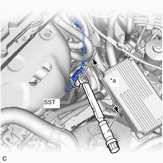
*a Torque Wrench Fulcrum Length Using SST, install the air fuel ratio sensor to the exhaust manifold converter sub-assembly.
- SST
- 09224-00011
- Torque:
- Specified tightening torque
- 44 N*m { 449 kgf*cm, 32 ft.*lbf }
Note
If the air fuel ratio sensor has been struck or dropped, replace it.
Tech Tips
-
Calculate the torque wrench reading when changing the fulcrum length of the torque wrench.
-
When using SST (fulcrum length of 30 mm (1.18 in.)) + torque wrench (fulcrum length of 255 mm (10.0 in.)):
39 N*m (398 kgf*cm, 29 ft.*lbf)
-
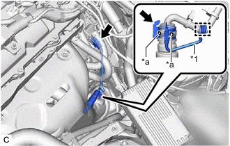
*1 Wire Harness Clamp Bracket *a Air Hole Install the wire harness clamp bracket to the air fuel ratio sensor and engage the clamp.
Tech Tips
Make sure the wire harness clamp bracket is not covering the air holes.
-
Connect the air fuel ratio sensor connector.
-
-
CONNECT GENERATOR CABLE (for RHD)
-
CONNECT MOTOR CABLE (for RHD)
-
INSTALL INVERTER TERMINAL COVER (for RHD)
-
INSTALL INVERTER MOTOR CABLE BRACKET ASSEMBLY (for RHD)
-
INSTALL SERVICE PLUG GRIP (for RHD)
-
INSPECT FOR EXHAUST GAS LEAK
-
PERFORM INITIALIZATION
-
Perform "Inspection After Repair" after replacing the air fuel ratio sensor.
-