HYBRID CONTROL SYSTEM DIAGNOSIS SYSTEM
-
DESCRIPTION
-
The hybrid vehicle control ECU assembly has a self-diagnosis system. If the computer, hybrid control system, or a component is not working properly, the ECU records the conditions that relate to the fault. The ECU also illuminates the master warning light in the combination meter assembly and provides other appropriate messages on the multi-information display, such as the HV system warning message, HV battery warning message, or discharge warning message.
Figure 1. for TFT Meter Type
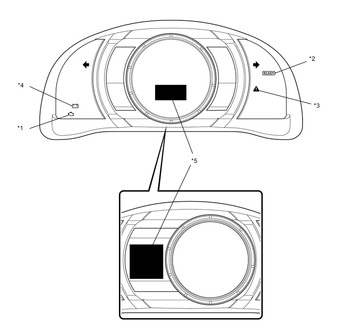
*1 MIL *2 READY Light *3 Master Warning Light *4 Charging Warning Light *5 Multi-information Display - - Figure 2. for Optitron Meter Type
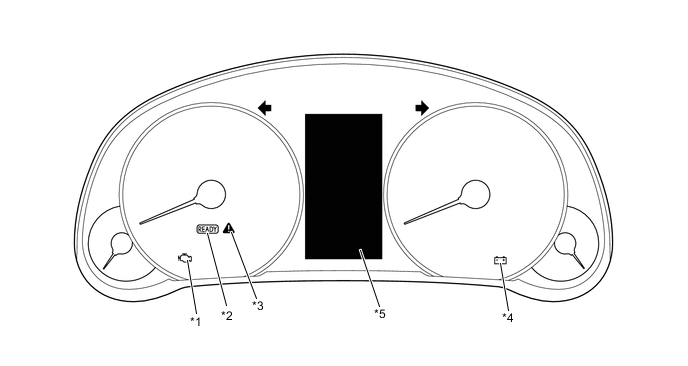
*1 MIL *2 READY Light *3 Master Warning Light *4 Charging Warning *5 Multi-information Display - - Tech Tips
The master warning light will illuminate when the hybrid control system is malfunctioning and the light will blink when in inspection mode.
-
-
2 TRIP DETECTION LOGIC
-
When a malfunction is first detected, the malfunction is temporarily stored in the hybrid vehicle control ECU assembly memory (1st trip). If the same malfunction is detected during the next drive cycle, the MIL is illuminated (2nd trip).
-
-
FREEZE FRAME DATA
-
The hybrid vehicle control ECU assembly records vehicle and driving condition information as freeze frame data the moment a DTC is stored. When troubleshooting, freeze frame data can be helpful in determining whether the vehicle was moving or stationary, whether the engine was warmed up or not, as well as other data recorded at the time of a malfunction.
-
-
AUXILIARY BATTERY VOLTAGE
-
If voltage is below 11 V, replace or recharge the auxiliary battery.
Note
After turning the power switch off, waiting time may be required before disconnecting the cable from the negative (-) auxiliary battery terminal. Therefore, make sure to read the disconnecting the cable from the negative (-) auxiliary battery terminal notices before proceeding with work.
-
-
MIL (Malfunction Indicator Lamp)
-
The MIL is illuminated when the power switch is first turned on (IG), before the READY light comes on.
-
When the READY indicator turns on, the MIL should turn off. If the MIL remains illuminated, the diagnosis system has detected a malfunction or abnormality in the system.
Tech Tips
If the MIL is not illuminated when the power switch is first turned on (IG), check the MIL circuit.
for SFI System: Click here
-
-
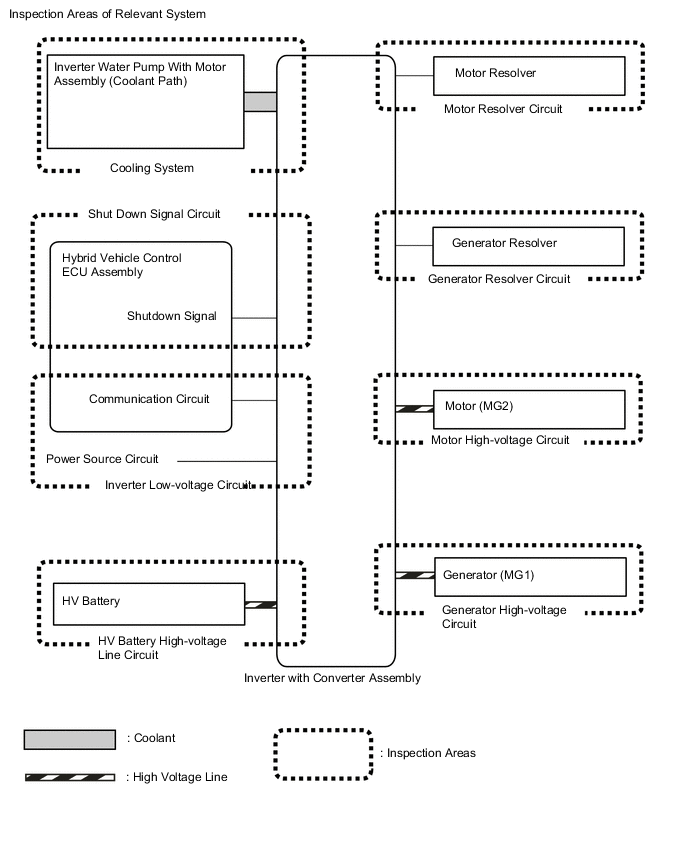
RELEVANT SYSTEMS CHECK
The inspection areas and outline of the inspection for each circuit are listed below.
Inspection Details of Relevant Systems System to be Inspected Malfunction Possibility Inspection Content Cooling System Temperature abnormally high
-
Grille blockage
-
Whether coolant is present
-
Whether there is a possibility that coolant was frozen when malfunction occurs
-
Cooling hose blockage
-
HV radiator fan operation
Shutdown Signal System Shutdown signal
-
Open or short circuit in shutdown signal communication line between hybrid vehicle control ECU assembly and motor generator ECU
Inverter Low-voltage Circuit Power supply voltage from +B or communication between hybrid vehicle control ECU assembly and motor generator control ECU
-
Open or short circuit in communication line between hybrid vehicle control ECU assembly and motor generator control ECU
-
Open or short circuit in the +B or ground lines
-
Fuse is blown
HV Battery High-voltage Line Circuit High voltage power supply from HV battery
-
Open or short circuit in the system main relay, connectors or cables
Motor Resolver Circuit Motor resolver signal
-
Open or short circuit in the motor resolver, connectors or cables
Generator Resolver Circuit Generator resolver signal
-
Open or short circuit in the generator resolver, connectors or cables
Motor High-voltage Circuit Motor (MG2) output
-
Open or short circuit in the motor (MG2), connectors or cables
Generator High-voltage Circuit Generator (MG1) output
-
Open or short circuit in the generator (MG1), connectors or cables
-
-
DTC PRIORITY LEVEL AND TROUBLE AREAS
-
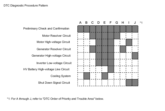
Each DTC diagnostic procedure for the hybrid control system consists of a combination of the various relevant system (circuit) inspections.
-
When multiple DTCs are output, performing each diagnostic procedure in order of priority can lead to a more accurate diagnosis.
Inspection Details of Relevant Systems DTC No. Detection Item Order of Priority Inspection Pattern 1 2 3 4 5 Microcomputer Malfunction Power Source Circuit Malfunction Communication System Malfunction Sensor and Actuator Circuit Malfunction System Malfunction P0069-273 Manifold Absolute Pressure - Barometric Pressure Correlation - - - ○ - - P0343-747 Camshaft Position Sensor "A" Circuit High Input - - - ○ - - P0516-769 Battery Temperature Sensor Circuit Low - - - ○ - - P0517-770 Battery Temperature Sensor Circuit High - - - ○ - - P0560-117 System Voltage - ○ - - - - P060B-134 Internal Control Module A/D Processing Performance ○ - - - - - P060B-135 Internal Control Module A/D Processing Performance ○ - - - - - P060B-570 Internal Control Module A/D Processing Performance ○ - - - - - P0617-142 Starter Relay Circuit High - - - ○ - - P062F-143 Internal Control Module EEPROM Error ○ - - - - - P06B0-163 Sensor Power Supply "A" Circuit / Open - ○ - - - - P06D6-511 Sensor Reference Voltage "F" Circuit / Open - ○ - - - - P06E6-164 Sensor Power Supply "C" Circuit / Open - ○ - - - - P0705-757 Transmission Range Sensor Circuit - - - ○ - - P0705-758 Transmission Range Sensor Circuit - - - ○ - - P0851-775 Park / Neutral Switch Input Circuit Low - - - ○ - - P0A01-726 Motor Electronics Coolant Temperature Sensor Circuit Range / Performance - - - ○ - B P0A02-719 Motor Electronics Coolant Temperature Sensor Circuit Low - - - ○ - - P0A03-720 Motor Electronics Coolant Temperature Sensor Circuit High - - - ○ - - P0A04-725 Motor Electronics Coolant Temperature Sensor Circuit Intermittent - - - ○ - B P0A08-264 DC / DC Converter Status Circuit - - - - ○ - P0A09-265 DC / DC Converter Status Circuit Low Input - - - ○ - - P0A09-591 DC / DC Converter Status Circuit Low Input - - - ○ - - P0A0D-350 High Voltage System Inter-Lock Circuit High - - - - ○ - P0A0D-351 High Voltage System Inter-Lock Circuit High - - - - ○ - P0A0F-204 Engine Failed to Start - - - ○ - - P0A0F-205 Engine Failed to Start - - - ○ - - P0A0F-206 Engine Failed to Start - - - ○ - - P0A0F-238 Engine Failed to Start - - - ○ - - P0A0F-524 Engine Failed to Start - - - ○ - - P0A0F-525 Engine Failed to Start - - - ○ - - P0A10-263 DC / DC Converter Status Circuit High Input - - - ○ - - P0A10-592 DC / DC Converter Status Circuit High Input - - - ○ - - P0A1A-151 Generator Control Module ○ - - - - - P0A1A-166 Generator Control Module ○ - - - - - P0A1A-517 Generator Control Module ○ - - - - A P0A1A-658 Generator Control Module ○ - - - - - P0A1A-791 Generator Control Module ○ - - - - - P0A1A-809 Generator Control Module ○ - - - - A P0A1B-198 Drive Motor "A" Control Module ○ - - - - - P0A1B-503 Drive Motor "A" Control Module ○ - - - - A P0A1B-505 Drive Motor "A" Control Module ○ - - - - A P0A1B-547 Drive Motor "A" Control Module ○ - - - - A P0A1B-554 Drive Motor "A" Control Module ○ - - - - A P0A1B-786 Drive Motor "A" Control Module ○ - - - - - P0A1B-794 Drive Motor "A" Control Module ○ - - - - - P0A1B-806 Drive Motor "A" Control Module ○ - - - - A P0A1D-144 Hybrid Powertrain Control Module ○ - - - - - P0A1D-148 Hybrid Powertrain Control Module ○ - - - - - P0A1D-162 Hybrid Powertrain Control Module ○ - - - - - P0A1D-187 Hybrid Powertrain Control Module ○ - - - - - P0A1D-721 Hybrid Powertrain Control Module ○ - - - - - P0A1D-722 Hybrid Powertrain Control Module ○ - - - - - P0A1D-723 Hybrid Powertrain Control Module ○ - - - - - P0A1D-787 Hybrid Powertrain Control Module ○ - - - - - P0A1D-818 Hybrid Powertrain Control Module ○ - - - - - P0A1D-821 Hybrid Powertrain Control Module ○ - - - - - P0A1D-822 Hybrid Powertrain Control Module ○ - - - - - P0A1D-823 Hybrid Powertrain Control Module ○ - - - - - P0A2B-250 Drive Motor "A" Temperature Sensor Circuit Range / Performance - - - ○ - - P0A2C-247 Drive Motor "A" Temperature Sensor Circuit Low - - - ○ - - P0A2D-249 Drive Motor "A" Temperature Sensor Circuit High - - - ○ - - P0A2E-248 Drive Motor "A" Temperature Sensor Circuit Intermittent - - - ○ - - P0A37-260 Generator Temperature Sensor Circuit Range / Performance - - - ○ - - P0A38-257 Generator Temperature Sensor Circuit Low - - - ○ - - P0A39-259 Generator Temperature Sensor Circuit High - - - ○ - - P0A3A-258 Generator Temperature Sensor Circuit Intermittent - - - ○ - - P0A3F-243 Drive Motor "A" Position Sensor Circuit - - - ○ - G P0A40-500 Drive Motor "A" Position Sensor Circuit Range / Performance - - - ○ - G P0A40-504 Drive Motor "A" Position Sensor Circuit Range / Performance - - - ○ - C P0A40-506 Drive Motor "A" Position Sensor Circuit Range / Performance - - - ○ - C P0A40-549 Drive Motor "A" Position Sensor Circuit Range / Performance - - - ○ - C P0A40-556 Drive Motor "A" Position Sensor Circuit Range / Performance - - - ○ - C P0A40-808 Drive Motor "A" Position Sensor Circuit Range / Performance - - - ○ - C P0A41-245 Drive Motor "A" Position Sensor Circuit Low - - - ○ - G P0A4B-253 Generator Position Sensor Circuit - - - ○ - H P0A4C-513 Generator Position Sensor Circuit Range / Performance - - - ○ - H P0A4C-518 Generator Position Sensor Circuit Range / Performance - - - ○ - C P0A4C-811 Generator Position Sensor Circuit Range / Performance - - - ○ - C P0A4D-255 Generator Position Sensor Circuit Low - - - ○ - H P0A51-174 Drive Motor "A" Current Sensor Circuit - - - ○ - - P0A78-113 Drive Motor "A" Inverter Performance - - - - ○ D P0A78-121 Drive Motor "A" Inverter Performance - - - - ○ F P0A78-128 Drive Motor "A" Inverter Performance - - - - ○ D P0A78-202 Drive Motor "A" Inverter Performance - - - - ○ - P0A78-279 Drive Motor "A" Inverter Performance - - - - ○ A P0A78-282 Drive Motor "A" Inverter Performance - - - - ○ A P0A78-284 Drive Motor "A" Inverter Performance - - - - ○ E P0A78-286 Drive Motor "A" Inverter Performance - - - - ○ E P0A78-287 Drive Motor "A" Inverter Performance - - - - ○ A P0A78-548 Drive Motor "A" Inverter Performance - - - - ○ A P0A78-555 Drive Motor "A" Inverter Performance - - - - ○ A P0A78-807 Drive Motor "A" Inverter Performance - - - - ○ A P0A7A-122 Generator Inverter Performance - - - - ○ D P0A7A-130 Generator Inverter Performance - - - - ○ D P0A7A-203 Generator Inverter Performance - - - - ○ - P0A7A-322 Generator Inverter Performance - - - - ○ E P0A7A-324 Generator Inverter Performance - - - - ○ E P0A7A-325 Generator Inverter Performance - - - - ○ A P0A7A-810 Generator Inverter Performance - - - - ○ A P0A90-251 Drive Motor "A" Performance - - - - ○ I P0A90-509 Drive Motor "A" Performance - - - - ○ I P0A92-261 Hybrid Generator Performance - - - - ○ J P0A92-521 Hybrid Generator Performance - - - - ○ J P0A93-346 Inverter Cooling System Performance - - - ○ - B P0A94-127 DC / DC Converter Performance - - - - ○ F P0A94-172 DC / DC Converter Performance - - - - ○ D P0A94-550 DC / DC Converter Performance - - - - ○ A P0A94-553 DC / DC Converter Performance - - - - ○ E P0A94-557 DC / DC Converter Performance - - - - ○ E P0AA1-231 Hybrid Battery Positive Contactor Circuit Stuck Closed - - - - ○ - P0AA1-233 Hybrid Battery Positive Contactor Circuit Stuck Closed - - - - ○ - P0AA4-232 Hybrid Battery Negative Contactor Circuit Stuck Closed - - - - ○ - P0AA6-526 Hybrid Battery Voltage System Isolation Fault - - - - ○ - P0AA6-611 Hybrid Battery Voltage System Isolation Fault - - - - ○ - P0AA6-612 Hybrid Battery Voltage System Isolation Fault - - - - ○ - P0AA6-613 Hybrid Battery Voltage System Isolation Fault - - - - ○ - P0AA6-614 Hybrid Battery Voltage System Isolation Fault - - - - ○ - P0AA7-727 Hybrid Battery Voltage Isolation Sensor Circuit - - - ○ - - P0AC0-817 Hybrid Battery Pack Current Sensor Circuit Range / Performance - - - ○ - - P0ADB-227 Hybrid Battery Positive Contactor Control Circuit Low - - - ○ - - P0ADC-226 Hybrid Battery Positive Contactor Control Circuit High - - - ○ - - P0ADF-229 Hybrid Battery Negative Contactor Control Circuit Low - - - ○ - - P0AE0-228 Hybrid Battery Negative Contactor Control Circuit High - - - ○ - - P0AE2-773 Hybrid Battery Precharge Contactor Circuit Stuck Closed - - - - ○ - P0AE6-225 Hybrid Battery Precharge Contactor Control Circuit Low - - - ○ - - P0AE7-224 Hybrid Battery Precharge Contactor Control Circuit High - - - ○ - - P0AEE-277 Motor Inverter Temperature Sensor "A" Circuit Range / Performance - - - ○ - B P0AEF-275 Drive Motor Inverter Temperature Sensor "A" Circuit Low - - - ○ - - P0AF0-274 Drive Motor Inverter Temperature Sensor "A" Circuit High - - - ○ - - P0AF1-276 Drive Motor Inverter Temperature Sensor "A" Circuit Intermittent / Erratic - - - ○ - B P0AF8-816 Hybrid Battery System Voltage - - - - ○ - P0AFC-150 Hybrid Battery Pack Sensor Module - ○ - - - - P0B23-129 Hybrid Battery "A" Voltage - - - ○ - - P0BCD-315 Generator Inverter Temperature Sensor Circuit Range / Performance - - - ○ - B P0BCE-313 Generator Inverter Temperature Sensor Circuit Low - - - ○ - - P0BCF-312 Generator Inverter Temperature Sensor Circuit High - - - ○ - - P0BD0-314 Generator Inverter Temperature Sensor Circuit Intermittent / Erratic - - - ○ - B P0BEA-290 Drive Motor "A" Phase V Current Sensor Circuit Range / Performance - - - ○ - A P0BEE-298 Drive Motor "A" Phase W Current Sensor Circuit Range / Performance - - - ○ - A P0C19-306 Drive Motor "A" Torque Delivered Performance - - - - ○ I P0C30-390 Hybrid Battery Pack State of Charge High - - - - ○ - P0C39-626 DC / DC Converter Temperature Sensor "A" Range / Performance - - - ○ - B P0C3A-621 DC / DC Converter Temperature Sensor "A" Low - - - ○ - - P0C3B-622 DC / DC Converter Temperature Sensor "A" High - - - ○ - - P0C3C-625 DC / DC Converter Temperature Sensor "A" Intermittent / Erratic - - - ○ - B P0C3E-628 DC / DC Converter Temperature Sensor "B" Range / Performance - - - ○ - B P0C3F-623 DC / DC Converter Temperature Sensor "B" Low - - - ○ - - P0C40-624 DC / DC Converter Temperature Sensor "B" High - - - ○ - - P0C41-627 DC / DC Converter Temperature Sensor "B" Intermittent / Erratic - - - ○ - B P0C73-776 Motor Electronics Coolant Pump "A" Control Performance - - - ○ - - P0C76-523 Hybrid Battery System Discharge Time Too Long - - - ○ - - P0CA3-442 DC/DC Converter Step Up Voltage Performance - - - - ○ A P0D2E-565 Drive Motor "A" Inverter Voltage Sensor Circuit Range / Performance - - - ○ - A P0D2E-586 Drive Motor "A" Inverter Voltage Sensor Circuit Range / Performance - - - ○ - - P0D2F-266 Drive Motor "A" Inverter Voltage Sensor Circuit Low - - - ○ - - P0D30-267 Drive Motor "A" Inverter Voltage Sensor Circuit High - - - ○ - - P0E05-328 Generator Phase V Current Sensor Circuit Range / Performance - - - ○ - A P0E09-336 Generator Phase W Current Sensor Circuit Range / Performance - - - ○ - A P0E32-564 DC/DC Converter Voltage Sensor "A" Range / Performance - - - ○ - A P0E32-585 DC/DC Converter Voltage Sensor "A" Range / Performance - - - ○ - - P0E33-589 DC/DC Converter Voltage Sensor "A" Low - - - ○ - - P0E34-590 DC/DC Converter Voltage Sensor "A" High - - - ○ - - P0E71-344 Generator Torque Delivered Performance - - - - ○ J P1606-308 Collision has been detected or Collision Sensor Connection (Open) - - - - - - P1606-317 Collision has been detected or Collision Sensor Connection (Open) - - - - - - P1C2A-155 Generator A/D Converter Circuit ○ - - - - - P1C2B-192 Drive Motor "A" A/D Converter Circuit ○ - - - - - P1C2D-587 Hybrid Battery Voltage / DC/DC Converter Voltage Correlation - - - - ○ - P1C3C-294 Drive Motor "A" Phase V Current Sensor Correlation - - - ○ - A P1C3D-302 Drive Motor "A" Phase W Current Sensor Correlation - - - ○ - A P1C3E-333 Generator Phase V Current Sensor Correlation - - - ○ - A P1C3F-341 Generator Phase W Current Sensor Correlation - - - ○ - A P1C4A-288 Drive Motor "A" Phase V Current Sensor Sub Circuit Range / Performance - - - ○ - A P1C4F-296 Drive Motor "A" Phase W Current Sensor Sub Circuit Range / Performance - - - ○ - A P1C54-326 Generator Phase V Current Sensor Sub Circuit Range / Performance - - - ○ - A P1C59-334 Generator Phase W Current Sensor Sub Circuit Range / Performance - - - ○ - A P1C6D-501 Drive Motor "A" Phase V Current Sensor Offset Range / Performance - - - ○ - A P1C6E-502 Drive Motor "A" Phase W Current Sensor Offset Range / Performance - - - ○ - A P1C71-515 Generator Phase V Current Sensor Offset Range / Performance - - - ○ - A P1C72-516 Generator Phase W Current Sensor Offset Range / Performance - - - ○ - A P1C73-512 Sensor Standard Voltage "F" Circuit / Open - ○ - - - - P1CA6-156 Generator Control Module Malfunction ○ - - - - - P1CA7-193 Drive Motor Control Module Malfunction ○ - - - - - P1CAC-200 Generator Position Sensor Angle Malfunction ○ - - - - - P1CAD-168 Drive Motor "A" Position Sensor Angle Malfunction ○ - - - - - P1CAF-792 Generator Position Sensor REF Signal Cycle Malfunction ○ - - - - - P1CB0-795 Drive Motor "A" Position Sensor REF Signal Cycle Malfunction ○ - - - - - P1CB2-793 Generator Position Sensor REF Signal Stop Malfunction ○ - - - - - P1CB3-796 Drive Motor "A" Position Sensor REF Signal Stop Malfunction ○ - - - - - P2120-152 Throttle / Pedal Position Sensor / Switch "D" Circuit - - - ○ - - P2121-106 Throttle / Pedal Position Sensor / Switch "D" Circuit Range / Performance - - - ○ - - P2122-104 Throttle / Pedal Position Sensor / Switch "D" Circuit Low Input - - - ○ - - P2123-105 Throttle / Pedal Position Sensor / Switch "D" Circuit High Input - - - ○ - - P2125-153 Throttle / Pedal Position Sensor / Switch "E" Circuit - - - ○ - - P2126-109 Throttle / Pedal Position Sensor / Switch "E" Circuit Range / Performance - - - ○ - - P2127-107 Throttle / Pedal Position Sensor / Switch "E" Circuit Low Input - - - ○ - - P2128-108 Throttle / Pedal Position Sensor / Switch "E" Circuit High Input - - - ○ - - P2138-110 Throttle / Pedal Position Sensor / Switch "D" / "E" Voltage Correlation - - - ○ - - P2138-154 Throttle / Pedal Position Sensor / Switch "D" / "E" Voltage Correlation - - - ○ - - P2228-268 Barometric Pressure Sensor "A" Circuit Low - - - ○ - - P2229-269 Barometric Pressure Sensor "A" Circuit High - - - ○ - - P2511-149 HV CPU Power Relay Sense Circuit Intermittent No Continuity ○ - - - - - P2532-772 Ignition Switch Run Position Circuit High ○ - - - - - P3000-388 Battery Control System - - - - ○ - P3000-389 Battery Control System - - - - ○ - P3000-603 Battery Control System - - - - ○ - P3004-131 High Voltage Power Resource - - - - ○ - P3004-132 High Voltage Power Resource - - - - ○ - P3004-133 High Voltage Power Resource - - - - ○ - P3004-800 High Voltage Power Resource - - - - ○ - P3004-801 High Voltage Power Resource - - - - ○ - P3004-803 High Voltage Power Resource - - - - ○ - P3107-213 Lost Communication with Airbag System Control Module - - ○ - - - P3107-214 Lost Communication with Airbag System Control Module - - ○ - - - P3107-215 Lost Communication with Airbag System Control Module - - ○ - - - P3108-536 Lost Communication with A/C System Control Module - - ○ - - - P3110-223 HV Main Relay - ○ - - - - P3133-659 Communication Error from Generator to Drive Motor "A" ○ - - - - - P3134-661 Communication Error from Drive Motor "A" to Generator ○ - - - - - P3147-239 Transmission system - - - - ○ - P3147-240 Transmission system - - - - ○ - P3147-241 Transmission system - - - - ○ - P3147-242 Transmission system - - - - ○ - P314A-828 Inverter Coolant Pump Speed Signal - - - ○ - - P321E-318 All HV Gate Blocking Range/Performance - - - ○ - - P321F-319 Part of HV Gate Blocking Range/Performance - - - ○ - - P324E-788 MG-ECU Power Relay Intermittent Circuit ○ - - - - - U0100-530 Lost Communication with ECM / PCM "A" - - ○ - - - U0110-159 Lost Communication with Drive Motor Control Module "A" - - ○ - - - U0110-160 Lost Communication with Drive Motor Control Module "A" - - ○ - - - U0110-656 Lost Communication with Drive Motor Control Module "A" - - ○ - - - U0110-657 Lost Communication with Drive Motor Control Module "A" - - ○ - - - U0129-527 Lost Communication with Brake System Control Module - - ○ - - - U0129-528 Lost Communication with Brake System Control Module - - ○ - - - U0140-146 Communication Error from Body ECU to HV ECU - - ○ - - - U0151-763 Communication Error from Airbag ECU to HV ECU - - ○ - - - U0164-827 Communication Error from A/C ECU to HV ECU - - ○ - - - U0424-537 Invalid Data Received from HVAC Control Module - - ○ - - - U1107-436 Lost Communication with Power Management Module - - ○ - - - Tech Tips
The "Example of Multiple DTCs being Output" below is only one example of a malfunction condition. Therefore, a determination should not be made based on this alone.
-
The power supply of the microcomputer decreases while the vehicle is being driven.
-
DTCs are detected and the vehicle behavior is as follows.
- Detected DTCs
-
P06B0-163 (Sensor Power Supply "A" Circuit / Open): Power Source Circuit Malfunction*
-
P0A40-500 (Drive Motor "A" Position Sensor Circuit Range / Performance): Sensor and actuator circuit malfunction*
-
P0A40-506 (Drive Motor "A" Position Sensor Circuit Range / Performance): Sensor and actuator circuit malfunction*
-
*: Check the priority level in the "DTC Order of Priority" chart above.
- Vehicle Behavior
-
System stopped
-
The inspection order of priority is: Microcomputer circuit → power source circuit → communication circuit → sensor and actuator circuit → system circuit. Therefore, check the repair procedure for P06B0-163.
-
Follow the repair procedures and replace the inverter assembly. Finish the repair.
Example of Multiple DTCs being Output:
It is possible to check only the specified malfunctioning parts without having to check irrelevant parts.
-