AIR CONDITIONING UNIT REASSEMBLY

PROCEDURE
-
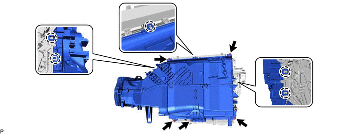
INSTALL HEATER CASE SUB-ASSEMBLY
-
Engage the 10 claws to install a new heater case sub-assembly.
-
-
INSTALL NO. 1 COOLER THERMISTOR
-
INSTALL NO. 1 COOLER EVAPORATOR SUB-ASSEMBLY
-
Sufficiently apply compressor oil to 2 new O-rings and the fitting surfaces of the No. 1 cooler evaporator sub-assembly.
Compressor Oil ND-OIL 11 or equivalent -
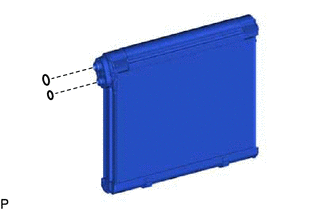
Install the 2 O-rings to the No. 1 cooler evaporator sub-assembly.
Note
Keep the O-rings and O-ring fitting surfaces free of foreign matter.
-
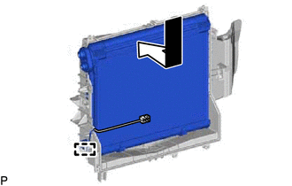
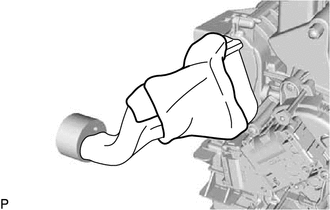
Install the No. 1 cooler evaporator sub-assembly with No. 1 cooler thermistor to the air duct as shown in the illustration.
-
Engage the clamp.
-
Engage the 5 claws.
-
Install the air duct with No. 1 cooler evaporator sub-assembly with the 5 screws.
-
-
INSTALL NO. 3 AIR CONDITIONING RADIATOR DAMPER SERVO SUB-ASSEMBLY
-
Install the No. 3 air conditioning radiator damper servo sub-assembly with the 3 screws.
Note
Make sure that each link guide pin of the No. 3 air conditioning radiator damper servo sub-assembly are inserted in each guide hole of the air conditioning radiator assembly.
-
-
INSTALL NO. 6 AIR CONDITIONING RADIATOR DAMPER SERVO SUB-ASSEMBLY
-
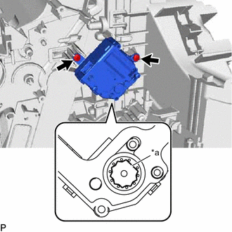
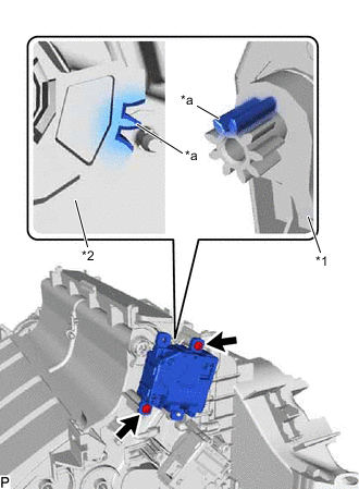
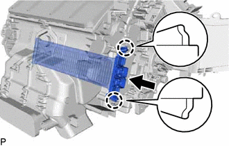
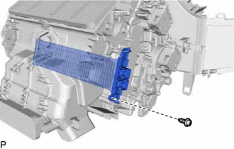
Using the reference points, install the No. 6 air conditioning radiator damper servo sub-assembly with the 2 screws.
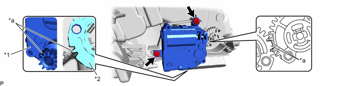
*1 No. 6 Air Conditioning Radiator Damper Servo Sub-assembly *2 Air Conditioning Radiator Assembly *a Reference Point - -
-
-
INSTALL NO. 5 AIR CONDITIONING RADIATOR DAMPER SERVO SUB-ASSEMBLY
-
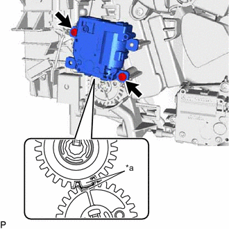
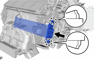
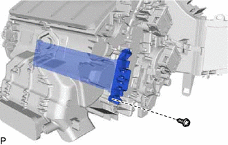
*a Reference Point Using the reference points, install the No. 5 air conditioning radiator damper servo sub-assembly with the 2 screws.
-
-
INSTALL NO. 2 AIR CONDITIONING RADIATOR DAMPER SERVO SUB-ASSEMBLY (for LH Side)
-
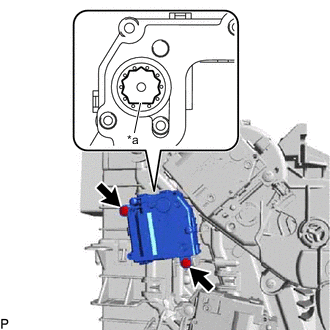
*a Reference Point Using the reference point, install the No. 2 air conditioning radiator damper servo sub-assembly with the 2 screws.
-
-
INSTALL NO. 4 AIR CONDITIONING RADIATOR DAMPER SERVO SUB-ASSEMBLY
-
Using the reference points, install the No. 4 air conditioning radiator damper servo sub-assembly with the 3 screws.
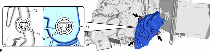
*1 No. 4 Air Conditioning Radiator Damper Servo Sub-assembly *2 Air Conditioning Radiator Assembly *a Reference Point - -
-
-
INSTALL NO. 2 AIR CONDITIONING RADIATOR DAMPER SERVO SUB-ASSEMBLY (for RH Side)
-
*a Reference Point Using the reference point, install the No. 2 air conditioning radiator damper servo sub-assembly with the 2 screws.
-
-
INSTALL NO. 1 AIR CONDITIONING RADIATOR DAMPER SERVO SUB-ASSEMBLY
-
*1 No. 1 Air Conditioning Radiator Damper Servo Sub-assembly *2 Air Conditioning Radiator Assembly *a Reference Point Using the reference points, install the No. 1 air conditioning radiator damper servo sub-assembly with the 2 screws.
-
-
INSTALL HEATER GROMMET
-
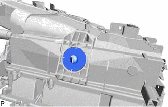
Install the heater grommet.
-
-
INSTALL NO. 4 COOLING UNIT PACKING
-
Remove any remaining No. 4 cooling unit packing from the air conditioner radiator assembly.
-
Remove the release paper from a new No. 4 cooling unit packing.
-
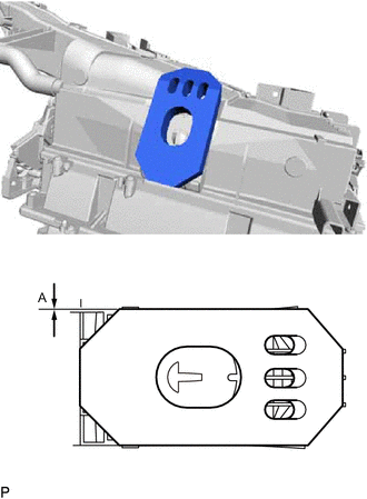
Install the No. 4 cooling unit packing as shown in the illustration.
Dimension Measurement A -3.0 to 3.0 mm (0.118 to 0.118 in.)
-
-
INSTALL HEATER COVER (w/o PTC Heater)
-
Engage the 2 claws to install the heater cover as shown in the illustration.
-
w/ Screw:
-
Install the screw.
-
-
-
INSTALL QUICK HEATER ASSEMBLY (w/ PTC Heater)
-
Engage the 2 claws to install the quick heater assembly as shown in the illustration.
-
w/ Screw:
-
Install the screw.
-
-
-
INSTALL HEATER PIPING COVER (for RHD)
-
Install the heater piping cover to the heater radiator unit sub-assembly.
-
-
INSTALL HEATER RADIATOR UNIT SUB-ASSEMBLY
-
for LHD:
-
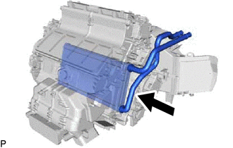
Install the heater radiator unit sub-assembly as shown in the illustration.
-
-
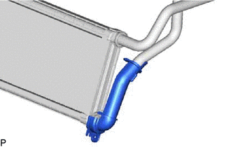
for RHD:
-
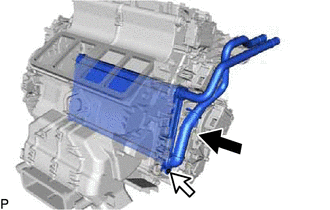
Install the heater radiator unit sub-assembly as shown in the illustration.
-
Install the screw.
-
-
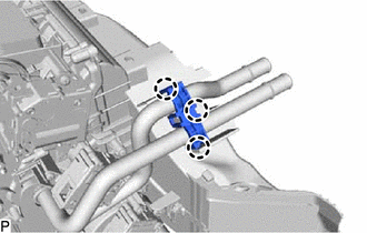
Engage the 3 claws to install the heater clamp.
-
-
INSTALL HEATER PACKING
-
Install the heater packing.
-
-
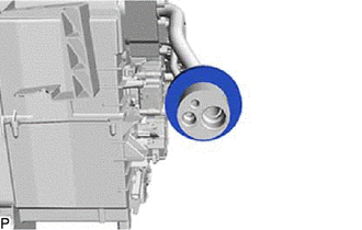
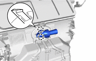
INSTALL COOLER EXPANSION VALVE
-
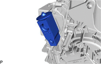
Install the cooler expansion valve.
-
-
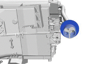
INSTALL AIR CONDITIONER TUBE AND ACCESSORY ASSEMBLY
-
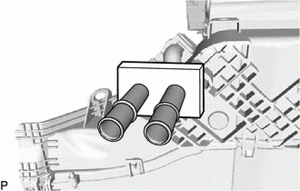
Remove the vinyl tape from the air conditioner tube and accessory assembly.
-
Sufficiently apply compressor oil to 2 new O-rings and the fitting surfaces of the air conditioner tube and accessory assembly.
Compressor Oil ND-OIL 11 or equivalent -
Install the 2 O-rings to the air conditioner tube and accessory assembly.
Note
Keep the O-rings and O-ring fitting surfaces free of foreign matter.
-
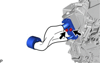
Using a 4 mm hexagon socket wrench, install the air conditioner tube and accessory assembly with the 2 hexagon bolts.
- Torque:
- 3.5 N*m { 36 kgf*cm, 31 in.*lbf }
-
-
INSTALL NO. 1 COOLING UNIT PACKING
-
Remove any remaining No. 1 cooling unit packing from the air conditioner tube and accessory assembly and cooler expansion valve.
-
Remove the release paper from a new No. 1 cooling unit packing.
-
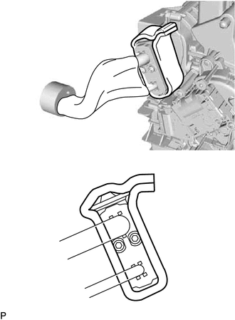
Install the No. 1 cooling unit packing as shown in the illustration.
-
-
INSTALL NO. 3 COOLING UNIT PACKING
-
Remove any remaining No. 3 cooling unit packing from the air conditioner tube and accessory assembly.
-
Remove the release paper from a new No. 3 cooling unit packing.
-
Install the No. 3 cooling unit packing.
-
-
INSTALL COOLER PLATE
-
Install the cooler plate.
-
-
INSTALL NO. 2 COOLING UNIT PACKING
-
Remove any remaining No. 2 cooling unit packing from the cooler plate.
-
Remove the release paper from a new No. 2 cooling unit packing.
-
Install the No. 2 cooling unit packing.
-
-
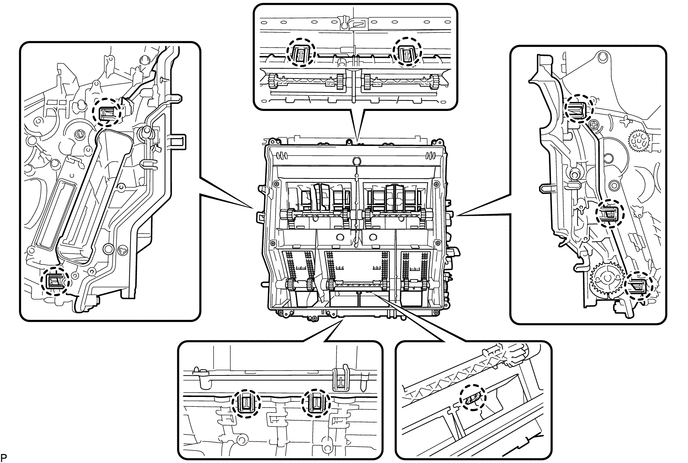
INSTALL AIR CONDITIONING HARNESS ASSEMBLY
-
Engage the clamp.
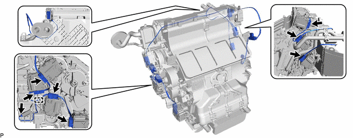
-
Connect each connector to install the air conditioning harness assembly.
-
-
INSTALL ASPIRATOR PIPE
-
Engage the 2 claws to install the aspirator pipe.
-
-
INSTALL AIR HOSE
-
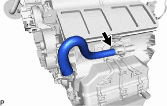
Install the air hose.
-
-
INSTALL LOWER DEFROSTER NOZZLE ASSEMBLY
-
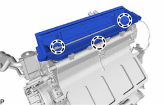
Engage the 3 claws to install the lower defroster nozzle assembly.
-
-
INSTALL BLOWER ASSEMBLY