HAZARD WARNING SWITCH INSPECTION
PROCEDURE
-
INSPECT RADIO RECEIVER ASSEMBLY (w/ Navigation System)
-
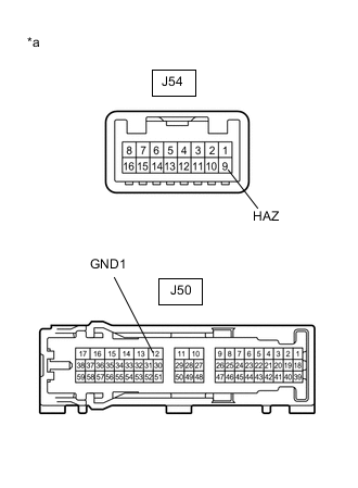
*a Component without harness connected
(Radio Receiver Assembly (Hazard Warning Signal Switch))
Measure the resistance according to the value(s) in the table below.
Standard Resistance Tester Connection Condition Specified Condition J54-9 (HAZ) - J50-12 (GND1) Hazard warning signal switch off 1 MΩ or higher Hazard warning signal switch on Below 125 Ω If the result is not as specified, replace the radio receiver assembly (hazard warning signal switch).
-
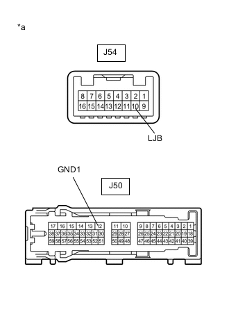
*a Component without harness connected
(Radio Receiver Assembly (Hazard Warning Signal Switch))
Hazard warning signal switch indicator inspection
-
Apply battery voltage to the radio receiver assembly (hazard warning signal switch) and check that the hazard warning signal switch indicator illuminates.
OK Condition Specified Condition Battery positive (+) → J54-10 (LJB)
Battery negative (-) → J50-12 (GND1)
Illuminates If the result is not as specified, replace the radio receiver assembly (hazard warning signal switch).
-
-
-
INSPECT RADIO RECEIVER ASSEMBLY (w/o Navigation System)
-
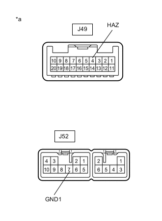
*a Component without harness connected
(Radio Receiver Assembly (Hazard Warning Signal Switch))
Measure the resistance according to the value(s) in the table below.
Standard Resistance Tester Connection Condition Specified Condition J49-4 (HAZ) - J52-7 (GND1) Hazard warning signal switch off 1 MΩ or higher Hazard warning signal switch on Below 125 Ω If the result is not as specified, replace the radio receiver assembly (hazard warning signal switch).
-
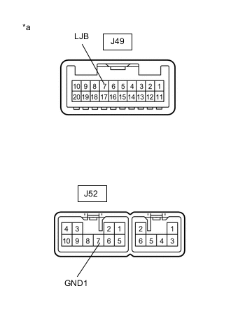
*a Component without harness connected
(Radio Receiver Assembly (Hazard Warning Signal Switch))
Hazard warning signal switch indicator inspection
-
Apply battery voltage to the radio receiver assembly (hazard warning signal switch) and check that the hazard warning signal switch indicator illuminates.
OK Condition Specified Condition Battery positive (+) → J49-7 (LJB)
Battery negative (-) → J52-7 (GND1)
Illuminates If the result is not as specified, replace the radio receiver assembly (hazard warning signal switch).
-
-