HEADLIGHT ASSEMBLY(for Single Beam Headlight) INSPECTION
PROCEDURE
-
INSPECT HEADLIGHT UNIT LH
-
Remove the headlight assembly LH.
-
Remove the headlight unit assembly LH from the headlight assembly LH.
-
Inspect the turn signal light circuit.
-
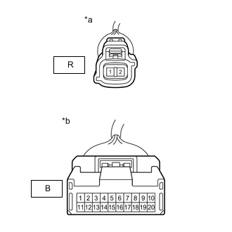
*a Component without harness connected
(to Turn Signal Light LH)
*b Component without harness connected
(to Headlight ECU Sub-assembly LH)
Measure the resistance according to the value(s) in the table below.
Standard Resistance Tester Connection Condition Specified Condition R-1 - B-9 Always Below 1 Ω R-3 - B-13 Always Below 1 Ω If the result is not as specified, replace the headlight unit LH.
-
-
Inspect the headlight leveling motor circuit.
-
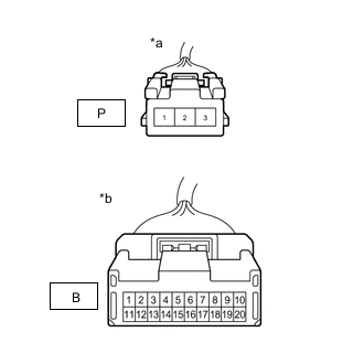
*a Component without harness connected
(to Headlight Levelimg Motor LH)
*b Component without harness connected
(to Headlight ECU Sub-assembly LH)
Measure the resistance according to the value(s) in the table below.
Standard Resistance Tester Connection Condition Specified Condition P-1 - B-17 Always Below 1 Ω P-2 - B-8 Always Below 1 Ω P-3 - B-7 Always Below 1 Ω If the result is not as specified, replace the headlight unit LH.
-
-
Inspect the Lo / Hi beam headlight light circuit.
-
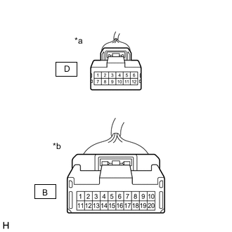
*a Component without harness connected
(to Headlight Unit Assembly LH)
*b Component without harness connected
(to Headlight ECU Sub-assembly LH)
Measure the resistance according to the value(s) in the table below.
Standard Resistance Tester Connection Condition Specified Condition D-5 - B-4 Always Below 1 Ω D-6 - B-5 Always Below 1 Ω If the result is not as specified, replace the headlight unit LH.
-
-
Inspect the Lo / Hi beam headlight switch circuit.
-
*a Component without harness connected
(to Headlight Unit Assembly LH)
*b Component without harness connected
(to Headlight ECU Sub-assembly LH)
Measure the resistance according to the value(s) in the table below.
Standard Resistance Tester Connection Condition Specified Condition D-10 - B-10 Always Below 1 Ω D-4 - B-1 Always Below 1 Ω If the result is not as specified, replace the headlight unit LH.
-
-
Inspect the headlight fan circuit.
-
*a Component without harness connected
(to Headlight Unit Assembly LH)
*b Component without harness connected
(to Headlight ECU Sub-assembly LH)
Measure the resistance according to the value(s) in the table below.
Standard Resistance Tester Connection Condition Specified Condition D-12- B-6 Always Below 1 Ω D-11 - B-15 Always Below 1 Ω D-4 - B-14 Always Below 1 Ω If the result is not as specified, replace the headlight unit LH.
-
-
Inspect the clearance light / daytime running light circuit.
-
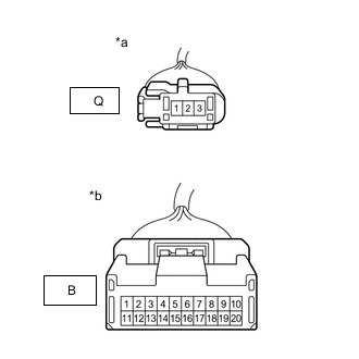
*a Component without harness connected
(to No. 1 Headlight Clearance LED Unit LH)
*b Component without harness connected
(to Headlight ECU Sub-assembly LH)
Measure the resistance according to the value(s) in the table below.
Standard Resistance Tester Connection Condition Specified Condition Q-2- B-20 Always Below 1 Ω Q-1 - B-16 Always Below 1 Ω Q-3 - B-11 Always Below 1 Ω If the result is not as specified, replace the headlight unit LH.
-
-
-
INSPECT HEADLIGHT UNIT RH
-
Remove the headlight assembly RH.
-
Remove the headlight unit assembly RH from the headlight assembly RH.
-
Inspect the turn signal light circuit.
-
*a Component without harness connected
(to Turn Signal Light RH)
*b Component without harness connected
(to Headlight ECU Sub-assembly RH)
Measure the resistance according to the value(s) in the table below.
Standard Resistance Tester Connection Condition Specified Condition R-1 - B-9 Always Below 1 Ω R-3 - B-13 Always Below 1 Ω If the result is not as specified, replace the headlight unit RH.
-
-
Inspect the headlight leveling motor circuit.
-
*a Component without harness connected
(to Headlight Levelimg Motor RH)
*b Component without harness connected
(to Headlight ECU Sub-assembly RH)
Measure the resistance according to the value(s) in the table below.
Standard Resistance Tester Connection Condition Specified Condition P-1 - B-17 Always Below 1 Ω P-2 - B-8 Always Below 1 Ω P-3 - B-7 Always Below 1 Ω If the result is not as specified, replace the headlight unit RH.
-
-
Inspect the Lo / Hi beam headlight light circuit.
-
*a Component without harness connected
(to Headlight Unit Assembly RH)
*b Component without harness connected
(to Headlight ECU Sub-assembly RH)
Measure the resistance according to the value(s) in the table below.
Standard Resistance Tester Connection Condition Specified Condition D-5 - B-4 Always Below 1 Ω D-6 - B-5 Always Below 1 Ω If the result is not as specified, replace the headlight unit RH.
-
-
Inspect the Lo / Hi beam headlight switch circuit.
-
*a Component without harness connected
(to Headlight Unit Assembly RH)
*b Component without harness connected
(to Headlight ECU Sub-assembly RH)
Measure the resistance according to the value(s) in the table below.
Standard Resistance Tester Connection Condition Specified Condition D-10 - B-10 Always Below 1 Ω D-4 - B-1 Always Below 1 Ω If the result is not as specified, replace the headlight unit RH.
-
-
Inspect the headlight fan circuit.
-
*a Component without harness connected
(to Headlight Unit Assembly RH)
*b Component without harness connected
(to Headlight ECU Sub-assembly RH)
Measure the resistance according to the value(s) in the table below.
Standard Resistance Tester Connection Condition Specified Condition D-12- B-6 Always Below 1 Ω D-11 - B-15 Always Below 1 Ω D-4 - B-14 Always Below 1 Ω If the result is not as specified, replace the headlight unit RH.
-
-
Inspect the clearance light / daytime running light circuit.
-
*a Component without harness connected
(to No. 1 Headlight Clearance LED Unit RH)
*b Component without harness connected
(to Headlight ECU Sub-assembly RH)
Measure the resistance according to the value(s) in the table below.
Standard Resistance Tester Connection Condition Specified Condition Q-2- B-20 Always Below 1 Ω Q-1 - B-16 Always Below 1 Ω Q-3 - B-11 Always Below 1 Ω If the result is not as specified, replace the headlight unit RH.
-
-