HEADLIGHT ASSEMBLY(for Triple Beam Headlight) REASSEMBLY
CAUTION / NOTICE / HINT
Tech Tips
-
Use the same procedure for the RH side and LH side.
-
The following procedure is for the LH side.
PROCEDURE
-
INSTALL HEADLIGHT FAN
-
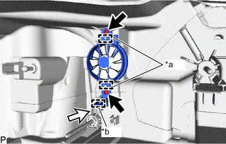
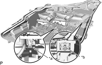
*a Guide *b Clamp Engage the 2 guides.
-
Install the headlight fan with the 2 screws.
-
Engage the clamp and connect the connector.
-
-
INSTALL HEADLIGHT LEVELING MOTOR
-
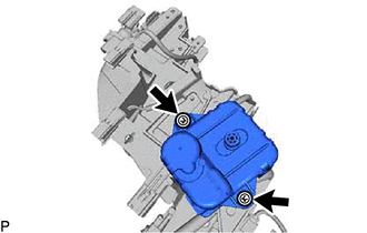
Install the headlight leveling motor to the headlight unit assembly with the 2 washers and 2 screws.
-
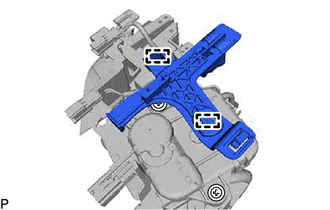
Engage the 2 guides to install the rail guide to the headlight leveling motor.
-
-
INSTALL HEADLIGHT UNIT ASSEMBLY
Note
-
Make sure to wear clean rubber gloves when performing this procedure.
-
Do not allow dirt or foreign matter to get on the headlight unit assembly or other components.
-
If there are any fingerprints or foreign matter on the headlight unit assembly or other components, wipe them off with a soft cloth.
-
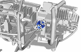
Engage the 2 claws to install the pivot collar to the headlight unit assembly.
-
*a Rail *b Aiming screw Align the headlight unit assembly with the rail and set the headlight unit assembly to the aiming screw.
-
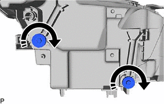

Turn in this Direction While holding the headlight unit assembly by hand, turn the aiming screws as shown in the illustration to temporarily install it.
Tech Tips
Turn the aiming screw the same number of times as it was turned during removal.
-
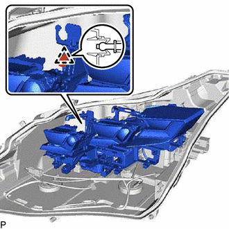
Engage the pivot collar to install the headlight unit assembly.
-
Engage the claw and 2 guides.
-
Install the center lens cover with the screw.
-
Engage the claw and 2 guides.
-
Install the inner lens cover with the screw.
-
Connect each connector.
-
-
INSTALL NO. 2 HEADLIGHT BACK COVER
Note
-
Make sure to wear clean rubber gloves when performing this procedure.
-
Do not allow dirt or foreign matter to get on the No. 2 headlight back cover or other components.
-
If there are any fingerprints or foreign matter on the No. 2 headlight back cover or other components, wipe them off with a soft cloth.
-
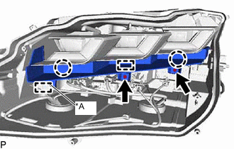
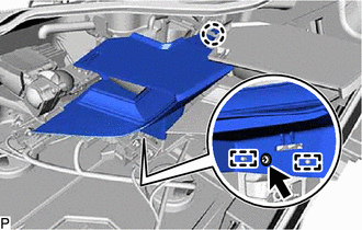
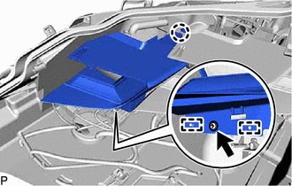
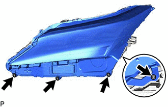
*A w/ Adaptive High Beam System Engage the 2 claws and guide.
-
Install the No. 2 headlight back cover with the 2 screws.
-
w/ Adaptive High Beam System:
-
Engage the clamp.
-
-
-
INSTALL HEADLIGHT LED UNIT ASSEMBLY
Note
-
Make sure to wear clean rubber gloves when performing this procedure.
-
Do not allow dirt or foreign matter to get on the headlight LED unit assembly or other components.
-
If there are any fingerprints or foreign matter on the headlight LED unit assembly or other components, wipe them off with a soft cloth.
-
Engage the 3 guides to temporarily install the headlight LED unit assembly.
-
Connect each connector.
-
-
INSTALL NO. 2 HEADLIGHT COVER
Note
-
Make sure to wear clean rubber gloves when performing this procedure.
-
Do not allow dirt or foreign matter to get on the No. 2 headlight cover or other components.
-
If there are any fingerprints or foreign matter on the No. 2 headlight cover or other components, wipe them off with a soft cloth.
-
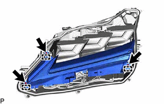
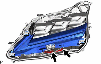
Engage the 3 guides.
-
Install the No. 2 headlight cover and headlight LED unit assembly with the 3 screws.
-
-
INSTALL HEADLIGHT LENS GASKET
-
Completely remove the old headlight lens gasket.
-
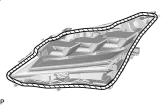

Cleaning Area Clean the installation groove of the headlight lens.
-
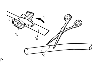
*a Release Paper *b Tape *c 45° Partially remove the release paper from a new headlight lens gasket, and cut off a piece of it.
-
Fold the release paper over the tip of a screwdriver and secure it in place with tape as indicated by the arrows, in the order shown in the illustration.
-
Using scissors, cut the end of the headlight lens gasket at a 45° angle.
-
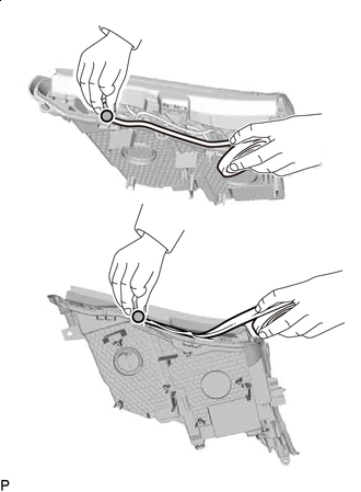

Starting Position Starting from the position shown in the illustration and moving counterclockwise, temporarily install the headlight lens gasket as shown in the illustration.
Note
Gently install the headlight lens gasket without pulling it.
-

Corner Groove Set the headlight lens gasket into the corner groove.
Note
-
Gently install the headlight lens gasket without pulling it.
-
If the headlight lens gasket is pulled while it is installed, it will not be installed properly in the corner groove.
-
-
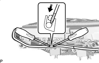
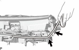
Press in this Direction Release Paper Using 2 screwdrivers with their tips wrapped with release paper, completely press the headlight lens gasket into the groove to install it.
Note
-
Gently install the headlight lens gasket without pulling it.
-
If the headlight lens gasket is pulled while it is installed, it will not be installed properly in the corner groove.
-
-
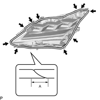
A 10 mm (0.394 in.) or more Corner Groove Repeat the following until the headlight lens gasket reaches the starting position: Temporarily install the headlight lens gasket to the straight groove and completely press it into the groove, and then temporarily install it to the corner groove and completely press it into the groove.
-
After installing the headlight lens gasket completely, check that the ends overlap for 10 mm (0.394 in.) or more.
-
Check the installation condition of the headlight lens gasket.
Note
-
Make sure the headlight lens gasket is not protruding and is installed properly.
-
Make sure there is no gap between the ends of the headlight lens gasket.
-
Make sure to thoroughly check the corners as the headlight lens gasket is likely to be improperly installed in the corners.
-
-
-
INSTALL HEADLIGHT LENS
Note
-
Make sure to wear clean rubber gloves when performing this procedure.
-
Do not allow dirt or foreign matter to get on the headlight lens.
-
If there are any fingerprints or foreign matter on the back of the headlight lens, wipe them off with a soft cloth.
-
Clean the sealing surface of the headlight lens.
-
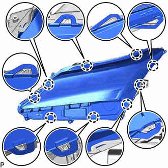
Engage the 9 claws to install the headlight lens to the housing.
Note
Make sure all of the claws are engaged.
-
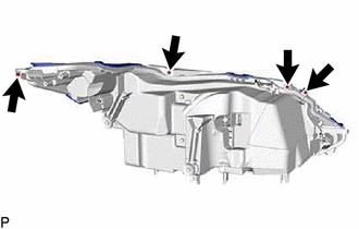
Install the 4 screws.
-
Using a T20H "TORX" driver, install the 4 "TORX" screws.
-
Check the installation condition of the headlight lens gasket.
Note
Make sure the headlight lens gasket is not protruding and completely contacts the headlight lens.
-
-
INSTALL HEADLIGHT GASKET (w/ Adaptive High Beam System)
-
INSTALL HEADLIGHT LIGHT CONTROL ECU SUB-ASSEMBLY (w/ Adaptive High Beam System)
-
INSTALL HEADLIGHT GASKET
-
INSTALL HEADLIGHT ECU SUB-ASSEMBLY