LIGHTING SYSTEM Power Source Circuit
DESCRIPTION
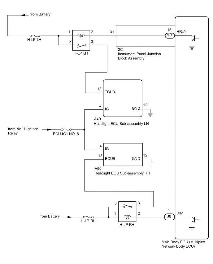
The main body ECU (multiplex network body ECU) receives IG signals and supplies power to the headlight ECU sub-assemblies via the H-LP relays.
WIRING DIAGRAM
CAUTION / NOTICE / HINT
Note
-
Inspect the fuses for circuits related to this system before performing the following inspection procedure.
-
Before replacing the main body ECU (multiplex network body ECU), refer to Service Bulletin.
-
The vehicle battery supplies power to the main body ECU (multiplex network body ECU) via the door control battery. Therefore, before proceeding with troubleshooting, perform an on-vehicle inspection and confirm that the main body ECU (multiplex network body ECU) power source circuit is normal.*
-
*: w/o Canister Pump Module with Door Ajar Warning Buzzer Function
PROCEDURE
-
CHECK HARNESS AND CONNECTOR (HEADLIGHT ECU SUB-ASSEMBLY - POWER SOURCE AND BODY GROUND)
-
Disconnect the A49 headlight ECU sub-assembly LH connector.
-
Disconnect the A50 headlight ECU sub-assembly RH connector.
-
Measure the voltage according to the value(s) in the table below.
Standard Voltage Headlight ECU sub-assembly LH Tester Connection Condition Specified Condition A49-13 (ECUB) - Body ground Engine switch on (IG) 11 to 14 V A49-4 (IG) - Body ground Engine switch on (IG) 11 to 14 V Headlight ECU sub-assembly RH Tester Connection Condition Specified Condition A50-13 (ECUB) - Body ground Engine switch on (IG) 11 to 14 V A50-4 (IG) - Body ground Engine switch on (IG) 11 to 14 V -
Measure the resistance according to the value(s) in the table below.
Standard Resistance Headlight ECU sub-assembly LH Tester Connection Condition Specified Condition A49-12 (GND) - Body ground Always Below 1 Ω Headlight ECU sub-assembly RH Tester Connection Condition Specified Condition A50-12 (GND) - Body ground Always Below 1 Ω Result Result Proceed to OK A NG (Headlight ECU Sub-assembly LH) B NG (Headlight ECU Sub-assembly RH) C
A 
PROCEED TO NEXT SUSPECTED AREA SHOWN IN PROBLEM SYMPTOMS TABLE Click here
C 
CHECK HARNESS AND CONNECTOR (POWER SOURCE - H-LP RH RELAY) Click here
B 
-
-
CHECK HARNESS AND CONNECTOR (POWER SOURCE - H-LP LH RELAY)
-
Remove the H-LP LH relay from the No. 1 engine room relay block and No. 1 junction block assembly.
-
Measure the voltage according to the value(s) in the table below.
Standard Voltage Tester Connection Condition Specified Condition Relay terminal 1 - Body ground Always 11 to 14 V Relay terminal 5 - Body ground Always 11 to 14 V Result Proceed to OK NG
NG
REPAIR OR REPLACE HARNESS OR CONNECTOR
OK
-
-
INSPECT H-LP LH RELAY
-
Inspect the H-LP LH relay.
Result Proceed to OK NG
NG
REPLACE H-LP LH RELAY
OK
-
-
CHECK HARNESS AND CONNECTOR (H-LP LH RELAY - HEADLIGHT ECU SUB-ASSEMBLY LH)
-
Measure the resistance according to the value(s) in the table below.
Standard Resistance Tester Connection Condition Specified Condition Relay terminal 3 - A49-13 (ECUB) Always Below 1 Ω Relay terminal 3 or A49-13 (ECUB) - Body ground Always 10 kΩ or higher Result Proceed to OK NG
NG
REPAIR OR REPLACE HARNESS OR CONNECTOR
OK
-
-
CHECK HARNESS AND CONNECTOR (H-LP LH RELAY - MAIN BODY ECU (MULTIPLEX NETWORK BODY ECU))
-
Disconnect the 2C instrument panel junction block assembly connector.
-
Measure the resistance according to the value(s) in the table below.
Standard Resistance Tester Connection Condition Specified Condition Relay terminal 2 - 2C-31 Always Below 1 Ω Relay terminal 2 or 2C-31 - Body ground Always 10 kΩ or higher Result Proceed to OK NG
NG
REPAIR OR REPLACE HARNESS OR CONNECTOR
OK
-
-
INSPECT INSTRUMENT PANEL JUNCTION BLOCK ASSEMBLY
-
Remove the instrument panel junction block assembly.
-
Remove the main body ECU (multiplex network body ECU) from the instrument panel junction block assembly.
-
Measure the resistance according to the value(s) in the table below.
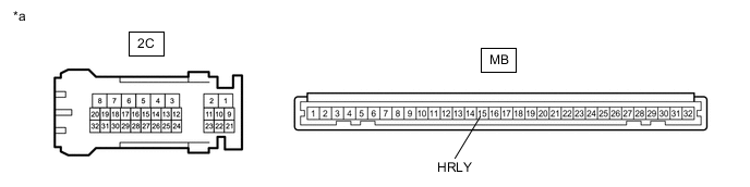
*a Component without harness connected
(Instrument Panel Junction Block Assembly)
- - Standard Resistance Tester Connection Condition Specified Condition 2C-31 - MB-15 (HRLY) Always Below 1 Ω Result Proceed to OK NG
OK
REPLACE MAIN BODY ECU (MULTIPLEX NETWORK BODY ECU) Click here
NG
REPLACE INSTRUMENT PANEL JUNCTION BLOCK ASSEMBLY Click here
-
-
CHECK HARNESS AND CONNECTOR (POWER SOURCE - H-LP RH RELAY)
-
Remove the H-LP RH relay from the No. 1 engine room relay block and No. 1 junction block assembly.
-
Measure the voltage according to the value(s) in the table below.
Standard Voltage Tester Connection Condition Specified Condition Relay terminal 1 - Body ground Always 11 to 14 V Relay terminal 5 - Body ground Always 11 to 14 V Result Proceed to OK NG
NG
REPAIR OR REPLACE HARNESS OR CONNECTOR
OK
-
-
INSPECT H-LP RH RELAY
-
Inspect the H-LP RH relay.
Result Proceed to OK NG
NG
REPLACE H-LP RH RELAY
OK
-
-
CHECK HARNESS AND CONNECTOR (H-LP RH RELAY - HEADLIGHT ECU SUB-ASSEMBLY RH)
-
Measure the resistance according to the value(s) in the table below.
Standard Resistance Tester Connection Condition Specified Condition Relay terminal 3 - A50-13 (ECUB) Always Below 1 Ω Relay terminal 3 or A50-13 (ECUB) - Body ground Always 10 kΩ or higher Result Proceed to OK NG
NG
REPAIR OR REPLACE HARNESS OR CONNECTOR
OK
-
-
CHECK HARNESS AND CONNECTOR (H-LP RH RELAY - MAIN BODY ECU (MULTIPLEX NETWORK BODY ECU))
-
Disconnect the J8 main body ECU (multiplex network body ECU) connector.
-
Measure the resistance according to the value(s) in the table below.
Standard Resistance Tester Connection Condition Specified Condition Relay terminal 2 - J8-1 (DIM) Always Below 1 Ω Relay terminal 2 or J8-1 (DIM) - Body ground Always 10 kΩ or higher Result Proceed to OK NG
OK
REPLACE MAIN BODY ECU (MULTIPLEX NETWORK BODY ECU) Click here
NG
REPAIR OR REPLACE HARNESS OR CONNECTOR
-