WIPER AND WASHER SYSTEM Headlight Cleaner Motor and Relay Circuit
DESCRIPTION
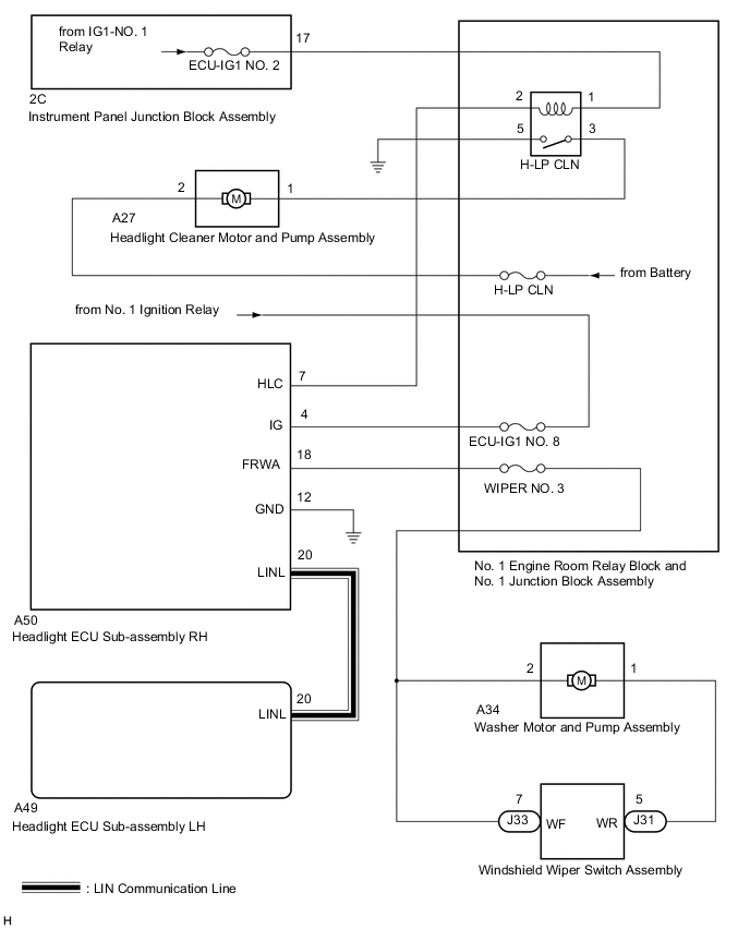
The headlight cleaner motor and pump assembly is controlled by the headlight ECU sub-assembly RH. When the headlight ECU sub-assembly RH receives the washer switch operation signal 5 times with the low beam headlights on, it operates the H-LP CLN relay once.
WIRING DIAGRAM
-
for Wiper Switch RH Side Type:
-
for Wiper Switch LH Side Type:

CAUTION / NOTICE / HINT
Note
Inspect the fuses of circuits related to this system before performing the following procedure.
PROCEDURE
-
PERFORM ACTIVE TEST USING GTS
-
Connect the GTS to the DLC3.
-
Turn the engine switch on (IG).
-
Turn the GTS on.
-
Enter the following menus: Body Electrical / (desired system) / Active Test.
-
Perform the Active Test according to the display on the GTS.
Body Electrical > AFS > Active TestTester Display Measurement Item Control Range Diagnostic Note Headlight Cleaner Function to operate the headlight cleaner motor OFF/ON *
-
*: for Triple Beam Headlight
Body Electrical > HL AutoLeveling > Active TestTester Display Measurement Item Control Range Diagnostic Note Headlight Cleaner Function to operate the headlight cleaner motor OFF/ON *
-
*: for Single Beam Headlight
Body Electrical > AFS > Active TestTester Display Headlight Cleaner
Body Electrical > HL AutoLeveling > Active TestTester Display Headlight Cleaner OK Headlight cleaner motor and pump assembly is normal. Result Proceed to OK NG -
NG 
INSPECT H-LP CLN RELAY Click here
OK 
-
-
READ VALUE USING GTS
-
Connect the GTS to the DLC3.
-
Turn the engine switch on (IG).
-
Turn the GTS on.
-
Enter the following menus: Body Electrical / (desired system) / Data List.
-
Read the Data List according to the display on the GTS.
Body Electrical > AFS > Data ListTester Display Measurement Item Range Normal Condition Diagnostic Note Front Window Washer Switch Washer switch ON position signal ON or OFF ON: Washer switch in ON position
OFF: Washer switch not in ON position
*
-
*: for Triple Beam Headlight
Body Electrical > HL AutoLeveling > Data ListTester Display Measurement Item Range Normal Condition Diagnostic Note Front Window Washer Switch Washer switch ON position signal ON or OFF ON: Washer switch in ON position
OFF: Washer switch not in ON position
*
-
*: for Single Beam Headlight
Body Electrical > AFS > Data ListTester Display Front Window Washer Switch
Body Electrical > HL AutoLeveling > Data ListTester Display Front Window Washer Switch OK The GTS display changes correctly in response to the front washer switch operation. Result Proceed to OK NG -
OK 
REPLACE HEADLIGHT ECU SUB-ASSEMBLY RH Click here
NG
-
-
CHECK HARNESS AND CONNECTOR (HEADLIGHT ECU SUB-ASSEMBLY - WINDSHIELD WIPER SWITCH ASSEMBLY)
-
Disconnect the A50 headlight ECU sub-assembly RH connector.
-
Disconnect the J33 windshield wiper switch assembly connector.
-
Measure the resistance according to the value(s) in the table below.
Standard Resistance for Wiper Switch RH Side Type Tester Connection Condition Specified Condition A50-18 (FRWA) - J33-7 (WF) Always Below 1 Ω A50-18 (FRWA) or J33-7 (WF) - Body ground Always 10 kΩ or higher for Wiper Switch LH Side Type Tester Connection Condition Specified Condition A50-18 (FRWA) - J33-4 (WF) Always Below 1 Ω A50-18 (FRWA) or J33-4 (WF) - Body ground Always 10 kΩ or higher Result Proceed to OK NG
OK
REPLACE HEADLIGHT ECU SUB-ASSEMBLY RH Click here
NG
REPAIR OR REPLACE HARNESS OR CONNECTOR
-
-
INSPECT H-LP CLN RELAY
-
Remove the H-LP CLN relay.
-
Inspect the H-LP CLN relay.
Result Proceed to OK NG
NG
REPLACE H-LP CLN RELAY
OK
-
-
CHECK HARNESS AND CONNECTOR (H-LP CLN RELAY - POWER SOURCE)
-
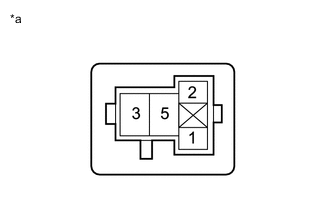
*a Front view of wire harness connector
(to H-LP CLN relay)
Measure the voltage according to the value(s) in the table below.
Standard Voltage Tester Connection Condition Specified Condition 1 - Body ground Engine switch off Below 1 V Engine switch on (IG) 11 to 14 V Result Proceed to OK NG
NG
REPAIR OR REPLACE HARNESS OR CONNECTOR
OK
-
-
CHECK HARNESS AND CONNECTOR (HEADLIGHT CLEANER MOTOR AND PUMP ASSEMBLY CIRCUIT)
-

*a Front view of wire harness connector
(to Headlight Cleaner Control Relay)
Remove the headlight cleaner control relay.
-
Using a service wire, connect terminal 3 and body ground.
Note
Do not forcibly insert the service wire into the terminals of the connector when connecting a service wire.
-
Check the headlight cleaner motor and pump assembly operate.
OK Headlight cleaner motor and pump assembly operate. Result Proceed to OK NG
NG
CHECK HARNESS AND CONNECTOR (HEADLIGHT CLEANER MOTOR AND PUMP ASSEMBLY - POWER SOURCE) Click here
OK
-
-
CHECK HARNESS AND CONNECTOR (H-LP CLN RELAY - BODY GROUND)
-
Measure the resistance according to the value(s) in the table below.
Standard Resistance Tester Connection Condition Specified Condition 5 - Body ground Always Below 1 Ω Result Proceed to OK NG
NG
REPAIR OR REPLACE HARNESS OR CONNECTOR
OK
-
-
CHECK HARNESS AND CONNECTOR (H-LP CLN RELAY - HEADLIGHT ECU SUB-ASSEMBLY RH)
-
Disconnect the A50 headlight ECU sub-assembly RH connector.
-
Measure the resistance according to the value(s) in the table below.
Standard Resistance Tester Connection Condition Specified Condition 2 - A50-7 (HLC) Always Below 1 Ω 2 or A50-7 (HLC) - Body ground Always 10 kΩ or higher Result Proceed to OK NG
OK
REPLACE HEADLIGHT ECU SUB-ASSEMBLY RH Click here
NG
REPAIR OR REPLACE HARNESS OR CONNECTOR
-
-
CHECK HARNESS AND CONNECTOR (HEADLIGHT CLEANER MOTOR AND PUMP ASSEMBLY - POWER SOURCE)
-
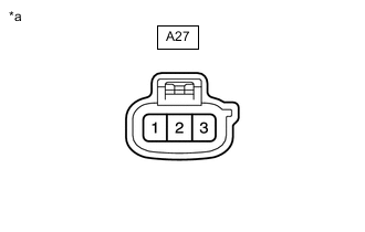
*a Front view of wire harness connector
(to Headlight Cleaner Motor and Pump Assembly)
Disconnect the A27 headlight cleaner motor and pump assembly connector.
-
Measure the voltage according to the value(s) in the table below.
Standard Voltage Tester Connection Condition Specified Condition A27-2 - Body ground Always 11 to 14 V Result Proceed to OK NG
NG
REPAIR OR REPLACE HARNESS OR CONNECTOR
OK
-
-
INSPECT HEADLIGHT CLEANER MOTOR AND PUMP ASSEMBLY
-
Inspect the headlight cleaner motor and pump assembly.
Result Proceed to OK NG
NG
REPLACE HEADLIGHT CLEANER MOTOR AND PUMP ASSEMBLY Click here
OK
-
-
CHECK HARNESS AND CONNECTOR (HEADLIGHT CLEANER MOTOR AND PUMP ASSEMBLY - H-LP CLN RELAY)
-
Disconnect the A27 headlight cleaner motor and pump assembly connector.
-
Remove the H-LP CLN relay.
-
Measure the resistance according to the value(s) in the table below.
Standard Resistance Tester Connection Condition Specified Condition A27-1 - 3 Always Below 1 Ω A27-1 or 3 - Body ground Always 10 kΩ or higher Result Proceed to OK NG
OK
USE SIMULATION METHOD TO CHECK Click here
NG
REPAIR OR REPLACE HARNESS OR CONNECTOR
-