WIPER AND WASHER SYSTEM Wiper Motor Power Source Circuit
DESCRIPTION
This circuit is the power source circuit for the combination meter assembly. This circuit provides two types of power sources; one is a constant power source, and the other is an IG power source.
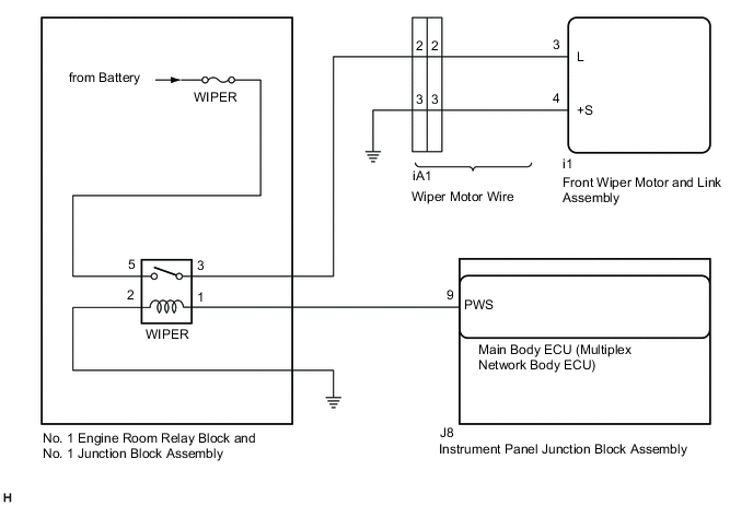
WIRING DIAGRAM
CAUTION / NOTICE / HINT
Note
Inspect the fuses of circuits related to this system before performing the following procedure.
PROCEDURE
-
READ VALUE USING GTS
-
Connect the GTS to the DLC3.
-
Turn the engine switch on (IG).
-
Turn the GTS on.
-
Enter the following menus: Body Electrical / Wiper / Data List.
-
Read the Data List according to the display on the GTS.
Body Electrical > Wiper > Data ListTester Display Measurement Item Range Normal Condition Diagnostic Note Status of Power Supply Voltage Front wiper motor and link assembly input voltage Normal or Abnormal Normal: 6.6 to 17.9 V
Abnormal: Below 6.5 V or 18.0 V Higher
-
Body Electrical > Wiper > Data ListTester Display Status of Power Supply Voltage OK The GTS display is normal. Result Proceed to OK NG
OK 
PROCEED TO NEXT SUSPECTED AREA SHOWN IN PROBLEM SYMPTOMS TABLE Click here
NG 
-
-
CHECK HARNESS AND CONNECTOR (FRONT WIPER MOTOR AND LINK ASSEMBLY - BODY GROUND)
-
Disconnect the i1 front wiper motor and link assembly connector.
-
Measure the resistance according to the value(s) in the table below.
Standard Resistance Tester Connection Condition Specified Condition i1-4 (+S) - Body ground Always Below 1 Ω Result Proceed to OK NG
NG 
CHECK WIPER MOTOR WIRE Click here
OK
-
-
CHECK HARNESS AND CONNECTOR (FRONT WIPER MOTOR AND LINK ASSEMBLY - POWER SOURCE)
-
Measure the voltage according to the value(s) in the table below.
Standard Voltage Tester Connection Condition Specified Condition i1-3 (L) - Body ground Engine switch off Below 1 V Engine switch on (IG) 11 to 14 V Result Proceed to OK NG
OK
REPLACE FRONT WIPER MOTOR AND LINK ASSEMBLY Click here
NG
-
-
CHECK WIPER MOTOR WIRE
-
Remove the wiper motor wire.
-
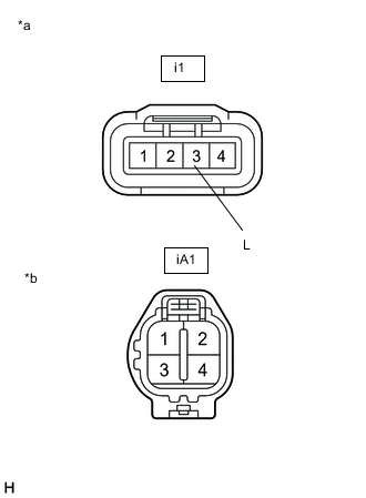
*a Front view of wire harness connector
(to Front Wiper Motor and Link Assembly)
*b Front view of wire harness connector
(to Wire Harness)
Measure the resistance according to the value(s) in the table below.
Standard Resistance Tester Connection Condition Specified Condition i1-3 (L) - iA1-2 Always Below 1 Ω Result Proceed to OK NG
NG
REPLACE WIPER MOTOR WIRE Click here
OK
-
-
INSPECT WIPER RELAY
-
Remove the WIPER relay.
-
Inspect the WIPER relay.
Result Proceed to OK NG
NG
REPLACE WIPER RELAY Click here
OK
-
-
CHECK HARNESS AND CONNECTOR (FRONT WIPER MOTOR AND LINK ASSEMBLY - POWER SOURCE, BODY GROUND)
-
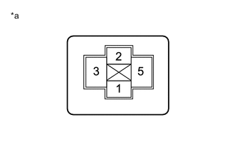
*a Front view of wire harness connector
(to WIPER relay)
Measure the voltage according to the value(s) in the table below.
Standard Voltage Tester Connection Condition Specified Condition 5 - Body ground Always 11 to 14 V -
Measure the resistance according to the value(s) in the table below.
Standard Resistance Tester Connection Condition Specified Condition 2 - Body ground Always Below 1 Ω Result Proceed to OK NG
NG
REPAIR OR REPLACE HARNESS OR CONNECTOR
OK
-
-
CHECK HARNESS AND CONNECTOR (WIPER RELAY - FRONT WIPER MOTOR AND LINK ASSEMBLY)
-
Measure the resistance according to the value(s) in the table below.
Standard Resistance Tester Connection Condition Specified Condition 3 - i1-3 (L) Always Below 1 Ω 3 or i1-3 (L) - Body ground Always 10 kΩ or higher Result Proceed to OK NG
NG
REPAIR OR REPLACE HARNESS OR CONNECTOR
OK
-
-
CHECK HARNESS AND CONNECTOR (WIPER RELAY - MAIN BODY ECU (MULTIPLEX NETWORK BODY ECU))
-
Disconnect the J8 main body ECU (multiplex network body ECU) connector.
-
Measure the resistance according to the value(s) in the table below.
Standard Resistance Tester Connection Condition Specified Condition 1 - J8-9 (PWS) Always Below 1 Ω 1 or J8-9 (PWS) - Body ground Always 10 kΩ or higher Result Proceed to OK NG
OK
REPLACE MAIN BODY ECU (MULTIPLEX NETWORK BODY ECU) Click here
NG
REPAIR OR REPLACE HARNESS OR CONNECTOR
-
-
CHECK WIPER MOTOR WIRE
-
Remove the wiper motor wire.
-
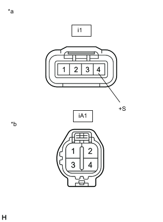
*a Front view of wire harness connector
(to Front Wiper Motor and Link Assembly)
*b Front view of wire harness connector
(to Wire Harness)
Measure the resistance according to the value(s) in the table below.
Standard Resistance Tester Connection Condition Specified Condition i1-4 (+S) - iA1-3 Always Below 1 Ω Result Proceed to OK NG
OK
REPAIR OR REPLACE HARNESS OR CONNECTOR
NG
REPLACE WIPER MOTOR WIRE Click here
-