WIPER AND WASHER SYSTEM Washer Nozzle Heater Circuit
DESCRIPTION
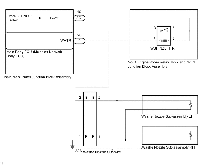
The main body ECU receives ambient air temperature information from the air conditioning amplifier assembly via CAN communication. The washer nozzle heater assembly controls the main body ECU and operates the washer nozzle heater assembly according to the ambient temperature.
WIRING DIAGRAM
CAUTION / NOTICE / HINT
Note
Inspect the fuses for circuits related to this system before performing the following inspection procedure.
PROCEDURE
-
PERFORM ACTIVE TEST USING GTS
-
Disconnect the A36 washer nozzle sub-assembly connector.
-
Connect the GTS to the DLC3.
-
Turn the engine switch on (IG).
-
Turn the GTS on.
-
Enter the following menus: Body Electrical / Main Body / Active Test.
-
Perform the Active Test according to the display on the GTS.
Body Electrical > Main Body > Active TestTester Display Measurement Item Control Range Diagnostic Note Washer Nozzle Heater Washer nozzle heater operation OFF/ON -
Body Electrical > Main Body > Active TestTester Display Washer Nozzle Heater -
Measure the voltage according to the value(s) in the table below.
Standard Voltage Tester Connection Switch Condition Specified Condition A36-2 (B) - Body ground Engine switch on, Active Test is not performed Below 1 V Engine switch on, Active Test is performed 11 to 14 V Result Proceed to OK NG
NG 
INSPECT WSH NZL HTR RELAY Click here
OK 
-
-
INSPECT WASHER NOZZLE SUB-ASSEMBLY
-
Remove the washer nozzle sub-assembly.
-
Inspect the washer nozzle sub-assembly.
Result Proceed to OK NG
OK 
REPAIR OR REPLACE HARNESS OR CONNECTOR
NG
REPLACE WASHER NOZZLE SUB-ASSEMBLY Click here
-
-
INSPECT WSH NZL HTR RELAY
-
Remove the WSH NZL HTR relay.
-
Inspect the WSH NZL HTR relay.
Result Proceed to OK NG
NG
REPLACE WSH NZL HTR RELAY
OK
-
-
CHECK HARNESS AND CONNECTOR (WSH NZL HTR RELAY - POWER SOUCE)
-
Measure the resistance according to the value(s) in the table below.
Standard Resistance Tester Connection Condition Specified Condition A36-2 (B) - WSH NZL HTR RELAY 3 Always Below 1 Ω A36-2 (B) or WSH NZL HTR RELAY 3 - Body ground Always 10 kΩ or higher Result Proceed to OK NG
NG
REPAIR OR REPLACE HARNESS OR CONNECTOR
OK
-
-
CHECK HARNESS AND CONNECTOR (MAIN BODY ECU (MULTIPLEX NETWORK BODY ECU) - WSH NZL HTR RELAY)
-
Disconnect the J9 main body ECU (multiplex network body ECU) connector.
-
Measure the resistance according to the value(s) in the table below.
Standard Resistance Tester Connection Condition Specified Condition J9-20 (WHTR) - WSH NZL HTR RELAY 1 Always Below 1 Ω J9-20 (WHTR) or WSH NZL HTR RELAY 1 - Body ground Always 10 kΩ or higher Result Proceed to OK NG
NG
REPAIR OR REPLACE HARNESS OR CONNECTOR
OK
-
-
CHECK HARNESS AND CONNECTOR (WASHER NOZZLE SUB-ASSEMBLY - WSH NZL HTR RELAY)
-
Measure the resistance according to the value(s) in the table below.
Standard Resistance Tester Connection Condition Specified Condition A36-2 (B) - WSH NZL HTR RELAY 3 Always Below 1 Ω A36-2 (B) or WSH NZL HTR RELAY 3 - Body ground Always 10 kΩ or higher Result Proceed to OK NG
OK
REPLACE MAIN BODY ECU Click here
NG
REPAIR OR REPLACE HARNESS OR CONNECTOR
-