REAR POWER SEAT CONTROL SYSTEM(for Third Row) Power Source Circuit
DESCRIPTION
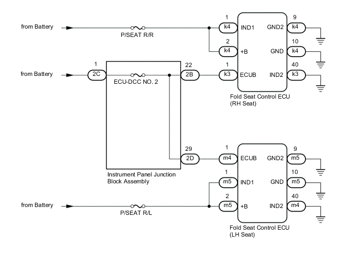
Power is supplied to each fold seat control ECU through fuses.
WIRING DIAGRAM
CAUTION / NOTICE / HINT
Note
Inspect the fuses for circuits related to this system before performing the following procedure.
PROCEDURE
-
CHECK REAR POWER SEAT CONTROL SYSTEM (for Third Row)
-
Check that the rear power seat control system (for Third Row) function operates normally.
Result Result Proceed to Fold/Return functions of both rear No. 2 power seats do not operate normally. A Fold/Return functions of rear No. 2 power seat RH do not operate normally. B Fold/Return functions of rear No. 2 power seat LH do not operate normally. C
B 
INSPECT INSTRUMENT PANEL JUNCTION BLOCK ASSEMBLY Click here
C
INSPECT INSTRUMENT PANEL JUNCTION BLOCK ASSEMBLY Click here
A 
-
-
CHECK HARNESS AND CONNECTOR (BATTERY POWER SUPPLY)
-
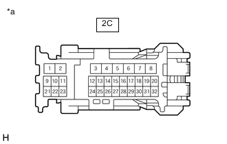
*a Front view of wire harness connector
(Instrument Panel Junction Block Assembly)
Disconnect the 2C instrument panel junction block assembly connector
-
Measure the voltage according to the value(s) in the table below.
Standard Voltage Tester Connection Condition Specified Condition 2C-1 - Body ground Always 11 to 14 V Result Proceed to OK NG
NG 
REPAIR OR REPLACE HARNESS OR CONNECTOR
OK
-
-
CHECK HARNESS AND CONNECTOR (BATTERY POWER SUPPLY)
-
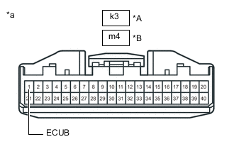
*A for RH seat *B for LH seat *a Front view of wire harness connector
(Fold Seat Control ECU (RH/LH Seat))
Disconnect the k3 fold seat control ECU (RH seat) connector.
-
Disconnect the m4 fold seat control ECU (LH seat) connector.
-
Measure the voltage according to the value(s) in the table below.
Standard Voltage Tester Connection Condition Specified Condition k3-1 (ECUB) - Body ground Always 11 to 14 V m4-1 (ECUB) - Body ground Always 11 to 14 V Result Proceed to OK NG
OK
PROCEED TO NEXT SUSPECTED AREA SHOWN IN PROBLEM SYMPTOMS TABLE Click here
NG
-
-
CHECK HARNESS AND CONNECTOR (INSTRUMENT PANEL JUNCTION BLOCK ASSEMBLY - FOLD SEAT CONTROL ECU (RH/LH SEAT))
-
Disconnect the 2B and 2D instrument panel junction block assembly connector
-
Measure the resistance according to the value(s) in the table below.
Standard Resistance Tester Connection Condition Specified Condition 2B-22 or k3-1 (ECUB) - Body ground Always 10 kΩ or higher 2D-29 or m4-1 (ECUB) - Body ground Always 10 kΩ or higher Result Proceed to OK NG
OK
REPLACE INSTRUMENT PANEL JUNCTION BLOCK ASSEMBLY Click here
NG
REPAIR OR REPLACE HARNESS OR CONNECTOR
-
-
INSPECT INSTRUMENT PANEL JUNCTION BLOCK ASSEMBLY
-
Measure the voltage according to the value(s) in the table below.
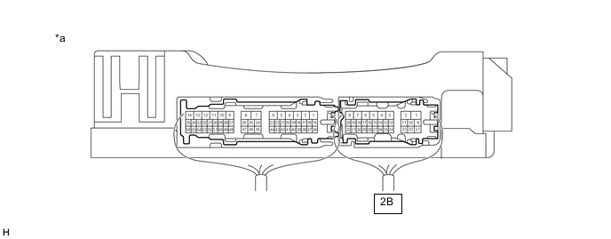
*a Component with harness connected
(Instrument Panel Junction Block Assembly)
- - Standard Voltage Tester Connection Condition Specified Condition 2B-22 - Body ground Always 11 to 14 V Result Proceed to OK NG
NG
REPLACE INSTRUMENT PANEL JUNCTION BLOCK ASSEMBLY Click here
OK
-
-
CHECK HARNESS AND CONNECTOR (INSTRUMENT PANEL JUNCTION BLOCK ASSEMBLY - FOLD SEAT CONTROL ECU (RH SEAT))
-
Disconnect the k3 fold seat control ECU (RH seat) connector.
-
Measure the resistance according to the value(s) in the table below.
Standard Resistance Tester Connection Condition Specified Condition 2B-22 - k3-1 (ECUB) Always Below 1 Ω Result Proceed to OK NG
NG
REPAIR OR REPLACE HARNESS OR CONNECTOR
OK
-
-
CHECK HARNESS AND CONNECTOR (FOLD SEAT CONTROL ECU (RH SEAT) - BATTERY POWER SUPPLY AND BODY GROUND)
-
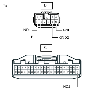
*a Front view of wire harness connector
(Fold Seat Control ECU (RH Seat))
Disconnect the k4 fold seat control ECU (RH seat) connector.
-
Measure the voltage and resistance according to the value(s) in the table below.
Standard Voltage Tester Connection Condition Specified Condition k4-1 (IND1) - Body ground Always 11 to 14 V k4-2 (+B) - Body ground Always 11 to 14 V -
Measure the resistance according to the value(s) in the table below.
Standard Resistance Tester Connection Condition Specified Condition k3-40 (IND2) - Body ground Always Below 1 Ω k4-9 (GND2) - Body ground Always Below 1 Ω k4-10 (GND) - Body ground Always Below 1 Ω Result Proceed to OK NG
OK
PROCEED TO NEXT SUSPECTED AREA SHOWN IN PROBLEM SYMPTOMS TABLE Click here
NG
REPAIR OR REPLACE HARNESS OR CONNECTOR
-
-
INSPECT INSTRUMENT PANEL JUNCTION BLOCK ASSEMBLY
-
Measure the voltage according to the value(s) in the table below
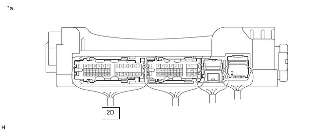
*a Component with harness connected
(Instrument Panel Junction Block Assembly)
- - Standard Voltage Tester Connection Condition Specified Condition 2D-29 - Body ground Always 11 to 14 V Result Proceed to OK NG
NG
REPLACE INSTRUMENT PANEL JUNCTION BLOCK ASSEMBLY Click here
OK
-
-
CHECK HARNESS AND CONNECTOR (INSTRUMENT PANEL JUNCTION BLOCK ASSEMBLY - FOLD SEAT CONTROL ECU (LH SEAT))
-
Disconnect the m4 fold seat control ECU (LH seat) connector.
-
Measure the resistance according to the value(s) in the table below.
Standard Resistance Tester Connection Condition Specified Condition m4-1 (ECUB) - 2D-29 Always Below 1 Ω Result Proceed to OK NG
NG
REPAIR OR REPLACE HARNESS OR CONNECTOR
OK
-
-
CHECK HARNESS AND CONNECTOR (FOLD SEAT CONTROL ECU (LH SEAT) - BATTERY POWER SUPPLY AND BODY GROUND)
-

*a Front view of wire harness connector
(Fold Seat Control ECU (LH Seat))
Disconnect the m5 fold seat control ECU (LH seat) connector.
-
Measure the voltage according to the value(s) in the table below.
Standard Voltage Tester Connection Condition Specified Condition m5-1 (IND1) - Body ground Always 11 to 14 V m5-2 (+B) - Body ground Always 11 to 14 V -
Measure the resistance according to the value(s) in the table below.
Standard Resistance Tester Connection Condition Specified Condition m4-40 (IND2) - Body ground Always Below 1 Ω m5-9 (GND2) - Body ground Always Below 1 Ω m5-10 (GND) - Body ground Always Below 1 Ω Result Proceed to OK NG
OK
PROCEED TO NEXT SUSPECTED AREA SHOWN IN PROBLEM SYMPTOMS TABLE Click here
NG
REPAIR OR REPLACE HARNESS OR CONNECTOR
-