REAR POWER SEAT CONTROL SYSTEM(for Third Row) Power Seat Motor Circuit
DESCRIPTION
When a switch of the fold seat switch assembly or No. 1 fold seat switch assembly is pushed, the fold seat control ECU receives a switch operation signal and operates each motor.
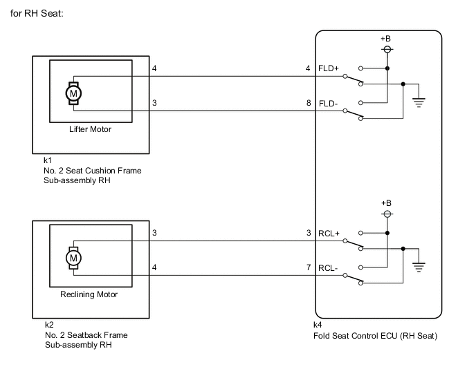
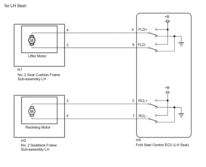
WIRING DIAGRAM
CAUTION / NOTICE / HINT
Note
-
When a fold seat control ECU (RH/LH seat) is replaced or removed and reinstalled, it is necessary to perform initialization.
-
When No. 2 seat cushion frame sub-assembly RH, No. 2 seat cushion frame sub-assembly LH, No. 2 seatback frame sub-assembly RH or No. 2 seatback frame sub-assembly LH is removed and reinstalled, it is necessary to perform initialization.
PROCEDURE
-
CHECK REAR POWER SEAT CONTROL SYSTEM (for Third Row)
-
Check that the rear power seat control system (for Third Row) function operates normally.
Result Result Proceed to Lifter motor (RH) does not operate normally. A Reclining motor (RH) does not operate normally. B Lifter motor (LH) does not operate normally. C Reclining motor (LH) does not operate normally. D
B 
INSPECT NO. 2 SEATBACK FRAME SUB-ASSEMBLY RH (RECLINING MOTOR) Click here
C
INSPECT NO. 2 SEAT CUSHION FRAME SUB-ASSEMBLY LH (LIFTER MOTOR) Click here
D
INSPECT NO. 2 SEATBACK FRAME SUB-ASSEMBLY LH (RECLINING MOTOR) Click here
A 
-
-
INSPECT NO. 2 SEAT CUSHION FRAME SUB-ASSEMBLY RH (LIFTER MOTOR)
-
Remove the No. 2 seat cushion frame sub-assembly RH.
-
Inspect the No. 2 seat cushion frame sub-assembly RH. (Lifter Motor)
Result Proceed to OK NG
NG 
REPLACE NO. 2 SEAT CUSHION FRAME SUB-ASSEMBLY RH Click here
OK
-
-
CHECK FOLD SEAT CONTROL ECU (RH SEAT)
-
Measure the voltage according to the value(s) in the table below.
Standard Voltage Tester Connection Condition Specified Condition k1-4 - Body ground Fold switch (RH) of fold seat switch assembly or No. 1 fold seat switch assembly pushed 11 to 14 V k1-3 - Body ground Return switch (RH) of fold seat switch assembly or No. 1 fold seat switch assembly pushed 11 to 14 V Result Proceed to OK NG
OK
PROCEED TO NEXT SUSPECTED AREA SHOWN IN PROBLEM SYMPTOMS TABLE Click here
NG
-
-
CHECK HARNESS AND CONNECTOR (FOLD SEAT CONTROL ECU (RH SEAT) - NO. 2 SEAT CUSHION FRAME SUB-ASSEMBLY RH)
-
Disconnect the k4 fold seat control ECU (RH seat) connector.
-
Measure the resistance according to the value(s) in the table below.
Standard Resistance Tester Connection Condition Specified Condition k4-4 (FLD+) - k1-4 Always Below 1 Ω k4-4 (FLD+) or k1-4 - Body ground Always 10 kΩ or higher k4-8 (FLD-) - k1-3 Always Below 1 Ω k4-8 (FLD-) or k1-3 - Body ground Always 10 kΩ or higher Result Proceed to OK NG
OK
REPLACE FOLD SEAT CONTROL ECU (RH SEAT) Click here
NG
REPAIR OR REPLACE HARNESS OR CONNECTOR
-
-
INSPECT NO. 2 SEATBACK FRAME SUB-ASSEMBLY RH (RECLINING MOTOR)
-
Remove the No. 2 seatback frame sub-assembly RH.
-
Inspect the No. 2 seatback frame sub-assembly RH. (Reclining Motor)
Result Proceed to OK NG
NG
REPLACE NO. 2 SEATBACK FRAME SUB-ASSEMBLY RH Click here
OK
-
-
CHECK FOLD SEAT CONTROL ECU (RH SEAT)
-
Measure the voltage according to the value(s) in the table below.
Standard Voltage Tester Connection Condition Specified Condition k2-3 - Body ground Fold switch (RH) of fold seat switch assembly or No. 1 fold seat switch assembly pushed 11 to 14 V k2-4 - Body ground Return switch (RH) of fold seat switch assembly or No. 1 fold seat switch assembly pushed 11 to 14 V Result Proceed to OK NG
OK
PROCEED TO NEXT SUSPECTED AREA SHOWN IN PROBLEM SYMPTOMS TABLE Click here
NG
-
-
CHECK HARNESS AND CONNECTOR (FOLD SEAT CONTROL ECU (RH SEAT) - NO. 2 SEATBACK FRAME SUB-ASSEMBLY RH)
-
Disconnect the k4 fold seat control ECU (RH seat) connector.
-
Measure the resistance according to the value(s) in the table below.
Standard Resistance Tester Connection Condition Specified Condition k4-3 (RCL+) - k2-3 Always Below 1 Ω k4-3 (RCL+) or k2-3 - Body ground Always 10 kΩ or higher k4-7 (RCL-) - k2-4 Always Below 1 Ω k4-7 (RCL-) or k2-4 - Body ground Always 10 kΩ or higher Result Proceed to OK NG
OK
REPLACE FOLD SEAT CONTROL ECU (RH SEAT) Click here
NG
REPAIR OR REPLACE HARNESS OR CONNECTOR
-
-
INSPECT NO. 2 SEAT CUSHION FRAME SUB-ASSEMBLY LH (LIFTER MOTOR)
-
Remove the No. 2 seat cushion frame sub-assembly LH.
-
Inspect the No. 2 seat cushion frame sub-assembly LH. (Lifter Motor)
Result Proceed to OK NG
NG
REPLACE NO. 2 SEAT CUSHION FRAME SUB-ASSEMBLY LH Click here
OK
-
-
CHECK FOLD SEAT CONTROL ECU (LH SEAT)
-
Measure the voltage according to the value(s) in the table below.
Standard Voltage Tester Connection Condition Specified Condition m1-4 - Body ground Fold switch (LH) of fold seat switch assembly or No. 1 fold seat switch assembly pushed 11 to 14 V m1-3 - Body ground Return switch (LH) of fold seat switch assembly or No. 1 fold seat switch assembly pushed 11 to 14 V Result Proceed to OK NG
OK
PROCEED TO NEXT SUSPECTED AREA SHOWN IN PROBLEM SYMPTOMS TABLE Click here
NG
-
-
CHECK HARNESS AND CONNECTOR (FOLD SEAT CONTROL ECU (LH SEAT) - NO. 2 SEAT CUSHION FRAME SUB-ASSEMBLY LH)
-
Disconnect the m5 fold seat control ECU (LH seat) connector.
-
Measure the resistance according to the value(s) in the table below.
Standard Resistance Tester Connection Condition Specified Condition m5-4 (FLD+) - m1-4 Always Below 1 Ω m5-4 (FLD+) or m1-4 - Body ground Always 10 kΩ or higher m5-8 (FLD-) - m1-3 Always Below 1 Ω m5-8 (FLD-) or m1-3 - Body ground Always 10 kΩ or higher Result Proceed to OK NG
OK
REPLACE FOLD SEAT CONTROL ECU (LH SEAT) Click here
NG
REPAIR OR REPLACE HARNESS OR CONNECTOR
-
-
INSPECT NO. 2 SEATBACK FRAME SUB-ASSEMBLY LH (RECLINING MOTOR)
-
Remove the No. 2 seatback frame sub-assembly LH.
-
Inspect the No. 2 seatback frame sub-assembly LH. (Reclining Motor)
Result Proceed to OK NG
NG
REPLACE NO. 2 SEATBACK FRAME SUB-ASSEMBLY LH Click here
OK
-
-
CHECK FOLD SEAT CONTROL ECU (LH SEAT)
-
Measure the voltage according to the value(s) in the table below.
Standard Voltage Tester Connection Condition Specified Condition m2-3 - Body ground Fold switch (LH) of fold seat switch assembly or No. 1 fold seat switch assembly pushed 11 to 14 V m2-4 - Body ground Return switch (LH) of fold seat switch assembly or No. 1 fold seat switch assembly pushed 11 to 14 V Result Proceed to OK NG
OK
PROCEED TO NEXT SUSPECTED AREA SHOWN IN PROBLEM SYMPTOMS TABLE Click here
NG
-
-
CHECK HARNESS AND CONNECTOR (FOLD SEAT CONTROL ECU (LH SEAT) - NO. 2 SEATBACK FRAME SUB-ASSEMBLY LH)
-
Disconnect the m5 fold seat control ECU (LH seat) connector.
-
Measure the resistance according to the value(s) in the table below.
Standard Resistance Tester Connection Condition Specified Condition m5-3 (RCL+) - m2-3 Always Below 1 Ω m5-3 (RCL+) or m2-3 - Body ground Always 10 kΩ or higher m5-7 (RCL-) - m2-4 Always Below 1 Ω m5-7 (RCL-) or m2-4 - Body ground Always 10 kΩ or higher Result Proceed to OK NG
OK
REPLACE FOLD SEAT CONTROL ECU (LH SEAT) Click here
NG
REPAIR OR REPLACE HARNESS OR CONNECTOR
-