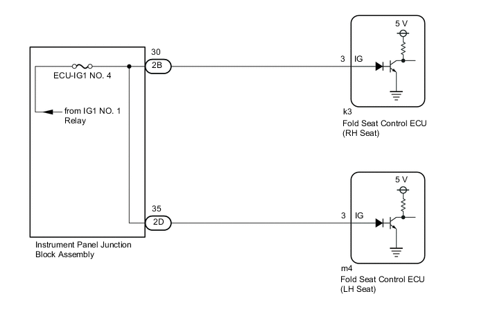
REAR POWER SEAT CONTROL SYSTEM(for Third Row) IG Signal Circuit
DESCRIPTION
Based on the engine switch signal, each fold seat control ECU determines the driving condition of the vehicle and enables or disables the fold and return functions.
WIRING DIAGRAM
CAUTION / NOTICE / HINT
Note
-
Inspect the fuses for circuits related to this system before performing the following procedure.
-
When the fold seat control ECU (RH/LH seat) is replaced, it is necessary to perform initialization.
PROCEDURE
-
CHECK REAR POWER SEAT CONTROL SYSTEM (for Third Row)
-
Check that the rear power seat control system (for Third Row) function operates normally.
Result Result Proceed to Fold/Return functions of both rear No. 2 power seats do not operate normally. A Fold/Return functions of rear No. 2 power seat RH do not operate normally. B Fold/Return functions of rear No. 2 power seat LH do not operate normally. C
B 
INSPECT INSTRUMENT PANEL JUNCTION BLOCK ASSEMBLY Click here
C
INSPECT INSTRUMENT PANEL JUNCTION BLOCK ASSEMBLY Click here
A 
-
-
CHECK HARNESS AND CONNECTOR (IG POWER SOURCE)
-
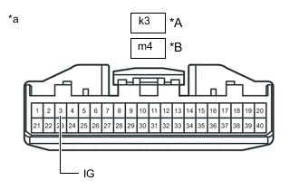
*A for RH seat *B for LH seat *a Front view of wire harness connector
(Fold Seat Control ECU (RH/LH Seat))
Disconnect the k3 fold seat control ECU (RH seat) connector.
-
Disconnect the m4 fold seat control ECU (LH seat) connector.
-
Measure the voltage according to the value(s) in the table below.
Standard Voltage Tester Connection Condition Specified Condition k3-3 (IG) - Body ground Engine switch off Below 1 V Engine switch on (IG) 11 to 14 V m4-3 (IG) - Body ground Engine switch off Below 1 V Engine switch on (IG) 11 to 14 V Result Proceed to OK NG
OK 
PROCEED TO NEXT SUSPECTED AREA SHOWN IN PROBLEM SYMPTOMS TABLE Click here
NG
-
-
CHECK HARNESS AND CONNECTOR (INSTRUMENT PANEL JUNCTION BLOCK ASSEMBLY - FOLD SEAT CONTROL ECU (RH/LH SEAT))
-
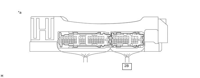
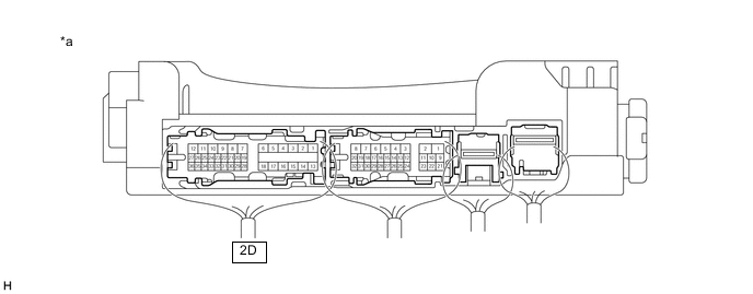
Disconnect the 2B and 2D instrument panel junction block assembly connectors.
-
Measure the resistance according to the value(s) in the table below.
Standard Resistance Tester Connection Condition Specified Condition 2B-30 or k3-3 (IG) - Body ground Always 10 kΩ or higher 2D-35 or m4-3 (IG) - Body ground Always 10 kΩ or higher Result Proceed to OK NG
OK
REPLACE INSTRUMENT PANEL JUNCTION BLOCK ASSEMBLY Click here
NG
REPAIR OR REPLACE HARNESS OR CONNECTOR
-
-
INSPECT INSTRUMENT PANEL JUNCTION BLOCK ASSEMBLY
-
Measure the voltage according to the value(s) in the table below.
*a Component with harness connected
(Instrument Panel Junction Block Assembly)
- - Standard Voltage Tester Connection Condition Specified Condition 2B-30 - Body ground Engine switch off Below 1 V Engine switch on (IG) 11 to 14 V Result Proceed to OK NG
NG
REPLACE INSTRUMENT PANEL JUNCTION BLOCK ASSEMBLY Click here
OK
-
-
CHECK HARNESS AND CONNECTOR (INSTRUMENT PANEL JUNCTION BLOCK ASSEMBLY - FOLD SEAT CONTROL ECU (RH SEAT))
-
Disconnect the k3 fold seat control ECU (RH seat) connector.
-
Disconnect the 2B instrument panel junction block assembly connector.
-
Measure the resistance according to the value(s) in the table below.
Standard Resistance Tester Connection Condition Specified Condition 2B-30 - k3-3 (IG) Always Below 1 Ω Result Proceed to OK NG
OK
PROCEED TO NEXT SUSPECTED AREA SHOWN IN PROBLEM SYMPTOMS TABLE Click here
NG
REPAIR OR REPLACE HARNESS OR CONNECTOR
-
-
INSPECT INSTRUMENT PANEL JUNCTION BLOCK ASSEMBLY
-
Measure the voltage according to the value(s) in the table below.
*a Component with harness connected
(Instrument Panel Junction Block Assembly)
- - Standard Voltage Tester Connection Condition Specified Condition 2D-35 - Body ground Engine switch off Below 1 V Engine switch on (IG) 11 to 14 V Result Proceed to OK NG
NG
REPLACE INSTRUMENT PANEL JUNCTION BLOCK ASSEMBLY Click here
OK
-
-
CHECK HARNESS AND CONNECTOR (INSTRUMENT PANEL JUNCTION BLOCK ASSEMBLY - FOLD SEAT CONTROL ECU (LH SEAT))
-
Disconnect the m4 fold seat control ECU (LH seat) connector.
-
Disconnect the 2D instrument panel junction block assembly connector.
-
Measure the resistance according to the value(s) in the table below.
Standard Resistance Tester Connection Condition Specified Condition 2D-35 - m4-3 (IG) Always Below 1 Ω Result Proceed to OK NG
OK
PROCEED TO NEXT SUSPECTED AREA SHOWN IN PROBLEM SYMPTOMS TABLE Click here
NG
REPAIR OR REPLACE HARNESS OR CONNECTOR
-