REAR POWER SEAT CONTROL SYSTEM(for Third Row) Park / Neutral Position Switch Circuit
DESCRIPTION
Each fold seat control ECU receives the driving condition signal and engine switch signal from the main body ECU (multiplex network body ECU) to determine the driving state of the vehicle and enable or disable the fold and return functions.
WIRING DIAGRAM
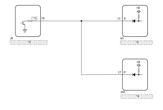
| *1 | SFTP |
| *2 | Main Body ECU (Multiplex Network Body ECU) |
| *3 | Fold Seat Control ECU (RH Seat) |
| *4 | Fold Seat Control ECU (LH Seat) |
CAUTION / NOTICE / HINT
Note
-
Before replacing the main body ECU (multiplex network body ECU), refer to Service Bulletin.
-
When a fold seat control ECU (RH/LH seat) is replaced, it is necessary to perform initialization.
PROCEDURE
-
CHECK REAR POWER SEAT CONTROL SYSTEM (for Third Row)
-
Check that the rear power seat control system (for Third Row) function operates normally.
Result Result Proceed to Fold/Return functions of both rear No. 2 power seats do not operate normally. A Fold/Return functions of rear No. 2 power seat RH do not operate normally. B Fold/Return functions of rear No. 2 power seat LH do not operate normally. C
B 
CHECK FOLD SEAT CONTROL ECU (RH SEAT) Click here
C
CHECK FOLD SEAT CONTROL ECU (LH SEAT) Click here
A 
-
-
CHECK HARNESS AND CONNECTOR (FOLD SEAT CONTROL ECU (RH/LH SEAT) - MAIN BODY ECU (MULTIPLEX NETWORK BODY ECU))
-
Disconnect the k3 fold seat control ECU (RH seat) connector.
-
Disconnect the m4 fold seat control ECU (LH seat) connector.
-
Disconnect the J9 main body ECU (multiplex network body ECU) connector.
-
Measure the resistance according to the value(s) in the table below.
Standard Resistance Tester Connection Condition Specified Condition k3-17 (P) or m4-17 (P) - J9-16 (SFTP) Always Below 1 Ω k3-17 (P), m4-17 (P) or J9-16 (SFTP) - Body ground Always 10 kΩ or higher Result Proceed to OK NG
NG 
REPAIR OR REPLACE HARNESS OR CONNECTOR
OK
-
-
CHECK MAIN BODY ECU (MULTIPLEX NETWORK BODY ECU)
-
Reconnect the k3 fold seat control ECU (RH seat) connector.
-
Reconnect the m4 fold seat control ECU (LH seat) connector.
-
Reconnect the J9 main body ECU (multiplex network body ECU) connector.
-
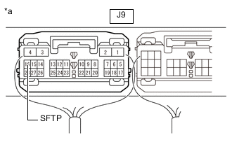
*a Component with harness connected
(Main Body ECU (Multiplex Network Body ECU))
Measure the voltage according to the value(s) in the table below.
Standard Voltage Tester Connection Condition Specified Condition J9-16 (SFTP) - Body ground Any of the following conditions are met:
-
Engine switch off
-
Engine switch on (IG) and vehicle speed 5 km/h (3.1 mph) or more
-
Engine switch on (IG), shift lever not in P, brake pedal not depressed and parking brake released
11 to 14 V Engine switch is on (IG) and any of the following conditions are met:
-
Vehicle speed below 5 km/h (3.1 mph) and shift lever in P
-
Vehicle speed below 5 km/h (3.1 mph) and brake pedal depressed
-
Vehicle speed below 5 km/h (3.1 mph) and parking brake applied
Below 1 V Result Proceed to OK NG -
OK
PROCEED TO NEXT SUSPECTED AREA SHOWN IN PROBLEM SYMPTOMS TABLE Click here
NG
REPLACE MAIN BODY ECU (MULTIPLEX NETWORK BODY ECU) Click here
-
-
CHECK FOLD SEAT CONTROL ECU (RH SEAT)
-
Disconnect the m4 fold seat control ECU (LH seat) connector.
-
Disconnect the J9 main body ECU (multiplex network body ECU) connector.
-
Measure the voltage according to the value(s) in the table below.
Standard Voltage Tester Connection Condition Specified Condition J9-16 (SFTP) - Body ground Always 11 to 14 V Result Proceed to OK NG
OK
PROCEED TO NEXT SUSPECTED AREA SHOWN IN PROBLEM SYMPTOMS TABLE Click here
NG
-
-
CHECK HARNESS AND CONNECTOR (FOLD SEAT CONTROL ECU (RH SEAT) - MAIN BODY ECU (MULTIPLEX NETWORK BODY ECU))
-
Disconnect the k3 fold seat control ECU (RH seat) connector.
-
Measure the resistance according to the value(s) in the table below.
Standard Resistance Tester Connection Condition Specified Condition k3-17 (P) - J9-16 (SFTP) Always Below 1 Ω Result Proceed to OK NG
OK
REPLACE FOLD SEAT CONTROL ECU (RH SEAT) Click here
NG
REPAIR OR REPLACE HARNESS OR CONNECTOR
-
-
CHECK FOLD SEAT CONTROL ECU (LH SEAT)
-
Disconnect the k3 fold seat control ECU (RH seat) connector.
-
Disconnect the J9 main body ECU (multiplex network body ECU) connector.
-
Measure the voltage according to the value(s) in the table below.
Standard Voltage Tester Connection Condition Specified Condition J9-16 (SFTP) - Body ground Always 11 to 14 V Result Proceed to OK NG
OK
PROCEED TO NEXT SUSPECTED AREA SHOWN IN PROBLEM SYMPTOMS TABLE Click here
NG
-
-
CHECK HARNESS AND CONNECTOR (FOLD SEAT CONTROL ECU (LH SEAT) - MAIN BODY ECU (MULTIPLEX NETWORK BODY ECU))
-
Disconnect the m4 fold seat control ECU (LH seat) connector.
-
Measure the resistance according to the value(s) in the table below.
Standard Resistance Tester Connection Condition Specified Condition m4-17 (P) - J9-16 (SFTP) Always Below 1 Ω Result Proceed to OK NG
OK
REPLACE FOLD SEAT CONTROL ECU (LH SEAT) Click here
NG
REPAIR OR REPLACE HARNESS OR CONNECTOR
-