REAR POWER SEAT CONTROL SYSTEM(for Third Row) TERMINALS OF ECU
-
CHECK FOLD SEAT CONTROL ECU (RH SEAT)

-
Disconnect the k3 and k4 fold seat control ECU (RH seat) connectors.
-
Measure the resistance and voltage according to the value(s) in the table below.
Terminal No.
(Symbol)
Wiring Color Terminal Description Condition Specified Condition k4-2 (+B) - Body ground W - Body ground Battery power supply Always 11 to 14 V k4-1 (IND1) - Body ground B - Body ground Battery power supply Always 11 to 14 V k3-1 (ECUB) - Body ground W - Body ground System power source Always 11 to 14 V k3-3 (IG) - Body ground B - Body ground IG switch signal Engine switch off Below 1 V Engine switch on (IG) 11 to 14 V k4-10 (GND) - Body ground W-B - Body ground Ground Always Below 1 Ω k4-9 (GND2) - Body ground W-B - Body ground Ground Always Below 1 Ω k3-40 (IND2) - Body ground W-B - Body ground System ground Always Below 1 Ω -
Reconnect the k3 and k4 fold seat control ECU (RH seat) connectors.
-
Measure the resistance and voltage according to the value(s) in the table below.
-
Using an oscilloscope, check the waveform.
Terminal No.
(Symbol)
Wiring Color Terminal Description Condition Specified Condition k4-4 (FLD+) - Body ground L - Body ground Lifter motor operation signal
(Fold)
Fold switch (RH) of fold seat switch assembly or No. 1 fold seat switch assembly released → pushed (Fold operation) Below 1 V → 11 to 14 V k4-8 (FLD-) - Body ground SB - Body ground Lifter motor operation signal
(Return)
Return switch (RH) of fold seat switch assembly or No. 1 fold seat switch assembly released → pushed (Return operation) Below 1 V → 11 to 14 V k3-11 (SV1) - k3-8 (SG1) R - G Lifter motor position sensor power source Engine switch off → Engine switch on (IG) Below 1 V → 5.5 to 10 V k3-10 (SFLD) - k3-8 (SG1) P - G Lifter motor position sensor signal Lifter motor (RH) operating (Fold/return operation) Pulse generation
(Hi: 5.5 to 10 V, Lo: Below 1 V)
k3-8(SG1) - Body ground G - Body ground Lifter motor position sensor ground Always Below 1 Ω k4-3 (RCL+) - Body ground L - Body ground Reclining motor operation signal
(Fold)
Fold switch (RH) of fold seat switch assembly or No. 1 fold seat switch assembly released → pushed (Fold operation) Below 1 V → 11 to 14 V k4-7 (RCL-) - Body ground SB - Body ground Reclining motor operation signal
(Fold)
Return switch (RH) of fold seat switch assembly or No. 1 fold seat switch assembly released → pushed (Return operation) Below 1 V → 11 to 14 V k3-31 (SV2) - k3-28 (SG2) R - G Reclining motor position sensor power source Engine switch off → Engine switch on (IG) Below 1 V → 5.5 to 10 V k3-9 (SRCL) - k3-28 (SG2) P - G Reclining motor position sensor signal Reclining motor (RH) operating (Fold/return operation) Pulse generation
(Hi: 5.5 to 10 V, Lo: Below 1 V)
k3-28 (SG2) - Body ground G - Body ground Reclining motor position sensor ground Always Below 1 Ω k3-25 (RCLR) - Body ground B - Body ground Fold seat switch assembly (return switch (RH)) operation signal Return switch (RH) of fold seat switch assembly released → pushed 11 to 14 V → Below 1 V k3-26 (RCLF) - Body ground L - Body ground Fold seat switch assembly (fold switch (RH)) operation signal Fold switch (RH) of fold seat switch assembly released → pushed 11 to 14 V → Below 1 V k3-7 (RTRN) - Body ground B - Body ground Fold seat switch assembly (return switch (RH)) operation signal Return switch (RH) of No. 1 fold seat switch assembly released → pushed 11 to 14 V → Below 1 V k3-12 (FOLD) - Body ground L - Body ground Fold seat switch assembly (fold switch (RH)) operation signal Fold switch (RH) of No. 1 fold seat switch assembly released → pushed 11 to 14 V → Below 1 V k3-17 (P) - Body ground GR - Body ground Driving condition signal Any of the following conditions are met:
-
Engine switch off
-
Engine switch on (IG) and vehicle speed 5 km/h (3.1 mph) or more
-
Engine switch on (IG), shift lever not in P, brake pedal not depressed and parking brake released
11 to 14 V Engine switch is on (IG) and any of the following conditions are met:
-
Vehicle speed below 5 km/h (3.1 mph) and shift lever in P
-
Vehicle speed below 5 km/h (3.1 mph) and brake pedal depressed
-
Vehicle speed below 5 km/h (3.1 mph) and parking brake applied
Below 1 V k3-18 (R CL) - Body ground P - Body ground Rear door courtesy light switch assembly (RH) input signal Rear door RH open → closed Below 1 V → 11 to 14 V k3-19 (BDCY) - Body ground R - Body ground Back door courtesy light switch assembly input signal Back door open → closed Below 1 V → 11 to 14 V -
-
-
CHECK FOLD SEAT CONTROL ECU (LH SEAT)

-
Disconnect the m4 and m5 fold seat control ECU (LH seat) connectors.
-
Measure the resistance and voltage according to the value(s) in the table below.
Terminal No.
(Symbol)
Wiring Color Terminal Description Condition Specified Condition m5-2 (+B) - Body ground W - Body ground Battery power supply Always 11 to 14 V m5-1 (IND1) - Body ground B - Body ground Battery power supply Always 11 to 14 V m4-1 (ECUB) - Body ground W - Body ground System power source Always 11 to 14 V m4-3 (IG) - Body ground B - Body ground IG switch signal Engine switch off Below 1 V Engine switch on (IG) 11 to 14 V m5-10 (GND) - Body ground W-B - Body ground Ground Always Below 1 Ω m5-9 (GND2) - Body ground W-B - Body ground Ground Always Below 1 Ω m4-40 (IND2) - Body ground W-B - Body ground System ground Always Below 1 Ω -
Reconnect the m4 and m5 fold seat control ECU (LH seat) connectors.
-
Measure the resistance and voltage according to the value(s) in the table below.
-
Using an oscilloscope, check the waveform.
Terminal No.
(Symbol)
Wiring Color Terminal Description Condition Specified Condition m5-4 (FLD+) - Body ground L - Body ground Lifter motor operation signal
(Fold)
Fold switch (LH) of fold seat switch assembly or No. 1 fold seat switch assembly released → pushed (Fold operation) Below 1 V → 11 to 14 V m5-8 (FLD-) - Body ground SB - Body ground Lifter motor operation signal
(Return)
Return switch (LH) of fold seat switch assembly or No. 1 fold seat switch assembly released → pushed (Return operation) Below 1 V → 11 to 14 V m4-11 (SV1) - m4-8 (SG1) R - G Lifter motor position sensor power source Engine switch off → Engine switch on (IG) Below 1 V → 5.5 to 10 V m4-10 (SFLD) - m4-8 (SG1) P - G Lifter motor position sensor signal Lifter motor (LH) operating (Fold/return operation) Pulse generation
(Hi: 5.5 to 10 V, Lo: Below 1 V)
m4-8(SG1) - Body ground G - Body ground Lifter motor position sensor ground Always Below 1 Ω m5-3 (RCL+) - Body ground L - Body ground Reclining motor operation signal
(Fold)
Fold switch (LH) of fold seat switch assembly or No. 1 fold seat switch assembly released → pushed (Fold operation) Below 1 V → 11 to 14 V m5-7 (RCL-) - Body ground SB - Body ground Reclining motor operation signal
(Fold)
Return switch (LH) of fold seat switch assembly or No. 1 fold seat switch assembly released → pushed (Return operation) Below 1 V → 11 to 14 V m4-31 (SV2) - m4-28 (SG2) R - B Reclining motor position sensor power source Engine switch off → Engine switch on (IG) Below 1 V → 5.5 to 10 V m4-9 (SRCL) - m4-28 (SG2) P - B Reclining motor position sensor signal Reclining motor (LH) operating (Fold/return operation) Pulse generation
(Hi: 5.5 to 10 V, Lo: Below 1 V)
m4-28 (SG2) - Body ground B - Body ground Reclining motor position sensor ground Always Below 1 Ω m4-25 (RCLR) - Body ground B - Body ground Fold seat switch assembly (return switch (LH)) operation signal Return switch (LH) of fold seat switch assembly released → pushed 11 to 14 V → Below 1 V m4-26 (RCLF) - Body ground L - Body ground Fold seat switch assembly (fold switch (LH)) operation signal Fold switch (LH) of fold seat switch assembly released → pushed 11 to 14 V → Below 1 V m4-7 (RTRN) - Body ground B - Body ground Fold seat switch assembly (return switch (LH)) operation signal Return switch (LH) of No. 1 fold seat switch assembly released → pushed 11 to 14 V → Below 1 V m4-12 (FOLD) - Body ground L - Body ground Fold seat switch assembly (fold switch (LH)) operation signal Fold switch (LH) of No. 1 fold seat switch assembly released → pushed 11 to 14 V → Below 1 V m4-17 (P) - Body ground GR - Body ground Driving condition signal Any of the following conditions are met:
-
Engine switch off
-
Engine switch on (IG) and vehicle speed 5 km/h (3.1 mph) or more
-
Engine switch on (IG), shift lever not in P, brake pedal not depressed and parking brake released
11 to 14 V Engine switch is on (IG) and any of the following conditions are met:
-
Vehicle speed below 5 km/h (3.1 mph) and shift lever in P
-
Vehicle speed below 5 km/h (3.1 mph) and brake pedal depressed
-
Vehicle speed below 5 km/h (3.1 mph) and parking brake applied
Below 1 V m4-18 (R CL) - Body ground P - Body ground Rear door courtesy light switch assembly (LH) input signal Rear door LH open → closed Below 1 V → 11 to 14 V m4-19 (BDCY) - Body ground R - Body ground Back door courtesy light switch assembly input signal Back door open → closed Below 1 V → 11 to 14 V -
-
-
CHECK MAIN BODY ECU (MULTIPLEX NETWORK BODY ECU) AND INSTRUMENT PANEL JUNCTION BLOCK ASSEMBLY
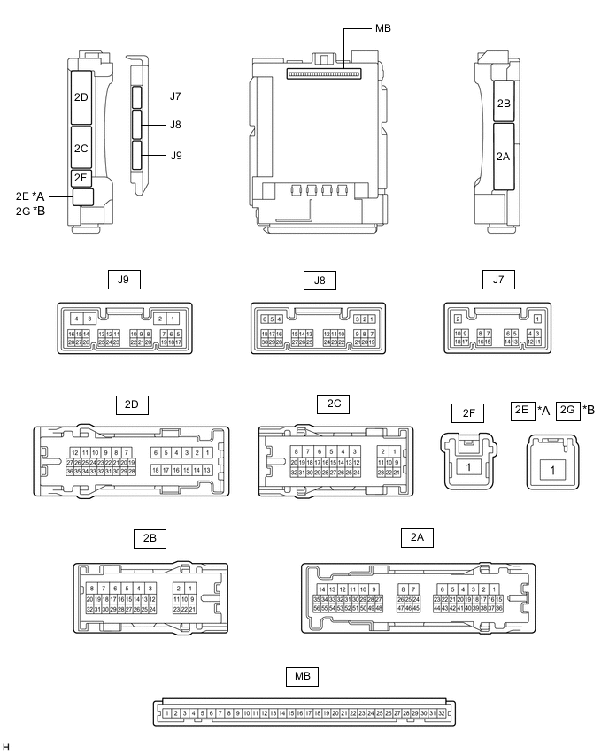
*A for LHD *B for RHD
-
Disconnect the MB main body ECU (multiplex network body ECU) connector.
-
Measure the voltage and resistance according to the value(s) in the table below.
Terminal No. (Symbol) Wiring Color Terminal Description Condition Specified Condition MB-31 (BECU) - Body ground - Battery power supply Always 11 to 14 V MB-32 (IG) - Body ground - IG power supply Engine switch off Below 1 V Engine switch on (IG) 11 to 14 V MB-11 (GND1) - Body ground - Ground Always Below 1 Ω -
Reconnect the MB main body ECU (multiplex network body ECU) connector.
-
Check for pulses according to the value(s) in the table below.
Terminal No. (Symbol) Wiring Color Terminal Description Condition Specified Condition J9-16 (SFTP) - Body ground - Driving condition signal Any of the following conditions are met:
-
Engine switch off
-
Engine switch on (IG) and vehicle speed 5 km/h (3.1 mph) or more
-
Engine switch on (IG), shift lever not in P, brake pedal not depressed and parking brake released
11 to 14 V Engine switch is on (IG) and any of the following conditions are met:
-
Vehicle speed below 5 km/h (3.1 mph) and shift lever in P
-
Vehicle speed below 5 km/h (3.1 mph) and brake pedal depressed
-
Vehicle speed below 5 km/h (3.1 mph) and parking brake applied
Below 1 V -
-