REAR POWER SEAT CONTROL SYSTEM(for Second Row) Rear Power Seat Switch Circuit
DESCRIPTION
Tech Tips
The rear power seat switch is a collective term for the rear power seat switch RH and the rear power seat switch LH.
When the rear power seat switch is operated, a recline signal is sent to the fold seat control ECU. The fold seat control ECU operates the reclining motor according to the received signal.
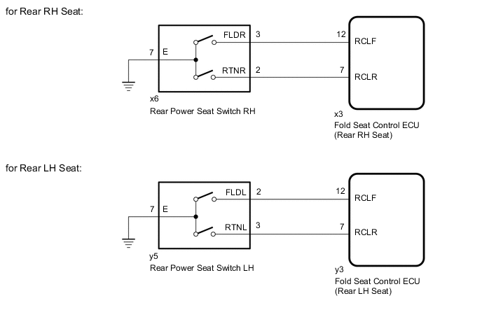
WIRING DIAGRAM
PROCEDURE
-
INSPECT REAR POWER SEAT SWITCH
-
Remove the rear power seat switch.
-
Inspect the rear power seat switch.
Result Result OK NG
NG 
REPLACE REAR POWER SEAT SWITCH Click here
OK 
-
-
CHECK HARNESS AND CONNECTOR (REAR POWER SEAT SWITCH - FOLD SEAT CONTROL ECU AND BODY GROUND)
-
Disconnect the x6*1 or y5*2 rear power seat switch connector.
-
*1: for Rear RH Seat
-
*2: for Rear LH Seat
-
-
Disconnect the x3*1 or y3*2 fold seat control ECU connector.
-
*1: for Rear RH Seat
-
*2: for Rear LH Seat
-
-
Measure the resistance according to the value(s) in the table below.
Standard Resistance for Rear RH Seat Tester Connection Condition Specified Condition x6-3 (FLDR) - x3-12 (RCLF) Always Below 1 Ω x6-3 (FLDR) or x3-12 (RCLF) - Body ground Always 10 kΩ or higher x6-2 (RTNR) - x3-7 (RCLR) Always Below 1 Ω x6-2 (RTNR) or x3-7 (RCLR) - Body ground Always 10 kΩ or higher x6-7 (E) - Body ground Always Below 1 Ω for Rear LH Seat Tester Connection Condition Specified Condition y5-2 (FLDL) - y3-12 (RCLF) Always Below 1 Ω y5-2 (FLDL) or y3-12 (RCLF) - Body ground Always 10 kΩ or higher y5-3 (RTNL) - y3-7 (RCLR) Always Below 1 Ω y5-3 (RTNL) or y3-7 (RCLR) - Body ground Always 10 kΩ or higher y5-7 (E) - Body ground Always Below 1 Ω Result Result OK NG
OK
GO TO PROBLEM SYMPTOMS TABLE Click here
NG
REPAIR OR REPLACE HARNESS OR CONNECTOR
-