REAR POWER SEAT CONTROL SYSTEM(for Second Row) Back Door Courtesy Switch Circuit
DESCRIPTION
The fold seat control ECU receives switch operation signals, the driving condition signal and back door courtesy light switch signal and operates the rear power seat according to these signals.
WIRING DIAGRAM
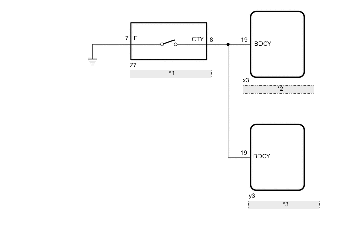
| *1 | Back Door Lock Assembly (Back Door Courtesy Light Switch) |
| *2 | Fold Seat Control ECU (Rear RH Seat) |
| *3 | Fold Seat Control ECU (Rear LH Seat) |
PROCEDURE
-
CHECK BACK DOOR LOCK ASSEMBLY (BACK DOOR COURTESY LIGHT SWITCH)
-
Check that the back door lock assembly (back door courtesy light switch) turns on and off according to the back door operation.
OK Back door lock assembly (back door courtesy light switch) turns on and off normally according to the back door operation. Result Proceed to OK NG
NG 
GO TO LIGHTING SYSTEM Click here
OK 
-
-
CHECK HARNESS AND CONNECTOR (BACK DOOR LOCK ASSEMBLY - FOLD SEAT CONTROL ECU AND BODY GROUND)
-
Disconnect the Z7 back door lock assembly connector.
-
Disconnect the x3*1 or y3*2 fold seat control ECU connector.
-
*1: for Rear RH Seat
-
*2: for Rear LH Seat
-
-
Measure the resistance according to the value(s) in the table below.
Standard Resistance for Rear RH Seat Tester Connection Condition Specified Condition Z7-8 (CTY) - x3-19 (BDCY) Always Below 1 Ω Z7-7 (E) - Body ground Always Below 1 Ω Z7-8 (CTY) or x3-19 (BDCY) - Body ground Always 10 kΩ or higher for Rear LH Seat Tester Connection Condition Specified Condition Z7-8 (CTY) - y3-19 (BDCY) Always Below 1 Ω Z7-7 (E) - Body ground Always Below 1 Ω Z7-8 (CTY) or y3-19 (BDCY) - Body ground Always 10 kΩ or higher Result Proceed to OK NG
OK
GO TO PROBLEM SYMPTOMS TABLE Click here
NG
REPAIR OR REPLACE HARNESS OR CONNECTOR
-