REAR POWER SEAT CONTROL SYSTEM(for Second Row) Park / Neutral Position Switch Circuit
DESCRIPTION
The fold seat control ECU receives switch operation signals, the back door courtesy light switch signal*1, rear door courtesy light switch assembly signal*2 and driving condition signal and operates the rear power seat according these signals.
-
*1: When using fold seat switch assembly
-
*2: When using rear power seat switch
WIRING DIAGRAM
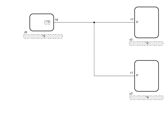
| *1 | SFTP |
| *2 | Main Body ECU (Multiplex Network Body ECU) |
| *3 | Fold Seat Control ECU (Rear RH Seat) |
| *4 | Fold Seat Control ECU (Rear LH Seat) |
CAUTION / NOTICE / HINT
Note
-
Before replacing the main body ECU (multiplex network body ECU), refer to Service Bulletin.
-
The vehicle battery supplies power to the main body ECU (multiplex network body ECU) via the door control battery. Therefore, before proceeding with troubleshooting, perform an on-vehicle inspection and confirm that the main body ECU (multiplex network body ECU) power source circuit is normal.*
-
*: w/o Canister Pump Module with Door Ajar Warning Buzzer Function
PROCEDURE
-
CHECK FOLD SEAT CONTROL ECU (PARK/NEUTRAL POSITION SWITCH SIGNAL)
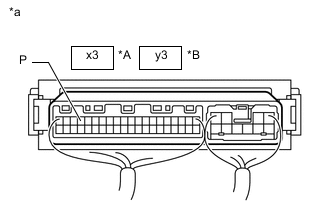
*A for Rear RH Seat *B for Rear LH Seat *a Component with harness connected
(Fold Seat Control ECU)
-
Remove the fold seat control ECU with its connectors still connected.
-
for Rear LH Seat: Click here
-
for Rear RH Seat: Click here
-
-
Measure the voltage according to the value(s) in the table below.
Standard Voltage for Rear RH Seat Tester Connection Condition Specified Condition x3-17 (P) - Body ground
-
Engine switch on (IG), shift lever in P or N → not in P or N
-
Engine switch on (IG), stop light switch assembly on → off
-
Engine switch on (IG), parking brake applied → released
11 to 14 V → Below 1 V Engine switch off 11 to 14 V for Rear LH Seat Tester Connection Condition Specified Condition y3-17 (P) - Body ground
-
Engine switch on (IG), shift lever in P or N → not in P or N
-
Engine switch on (IG), stop light switch assembly on → off
-
Engine switch on (IG), parking brake applied → released
11 to 14 V → Below 1 V Engine switch off 11 to 14 V Result Result OK NG -
OK 
GO TO PROBLEM SYMPTOMS TABLE Click here
NG 
-
-
CHECK HARNESS AND CONNECTOR (FOLD SEAT CONTROL ECU - MAIN BODY ECU (MULTIPLEX NETWORK BODY ECU))
-
Disconnect the x3*1 or y3*2 fold seat control ECU connector.
-
*1: for Rear RH Seat
-
*2: for Rear LH Seat
-
-
Disconnect the J9 main body ECU (multiplex network body ECU) connector.
-
Measure the resistance according to the value(s) in the table below.
Standard Resistance for Rear RH Seat Tester Connection Condition Specified Condition x3-17 (P) - J9-16 (SFTP) Always Below 1 Ω x3-17 (P) or J9-16 (SFTP) - Body ground Always 10 kΩ or higher for Rear LH Seat Tester Connection Condition Specified Condition y3-17 (P) - J9-16 (SFTP) Always Below 1 Ω y3-17 (P) or J9-16 (SFTP) - Body ground Always 10 kΩ or higher Result Result OK NG
NG
REPAIR OR REPLACE HARNESS OR CONNECTOR
OK
-
-
CHECK FOLD SEAT CONTROL ECU
-
Replace the fold seat control ECU with a new or known good one.
-
for Rear LH Seat: Click here
-
for Rear RH Seat: Click here
-
-
Check the operation of the rear power seat.
OK The rear power seat operates normally. Result Proceed to OK NG
OK
END (FOLD SEAT CONTROL ECU WAS DEFECTIVE)
NG
REPLACE MAIN BODY ECU (MULTIPLEX NETWORK BODY ECU) Click here
-