SEAT HEATER SYSTEM Seat Heater for Rear Right Seat does not Operate
DESCRIPTION
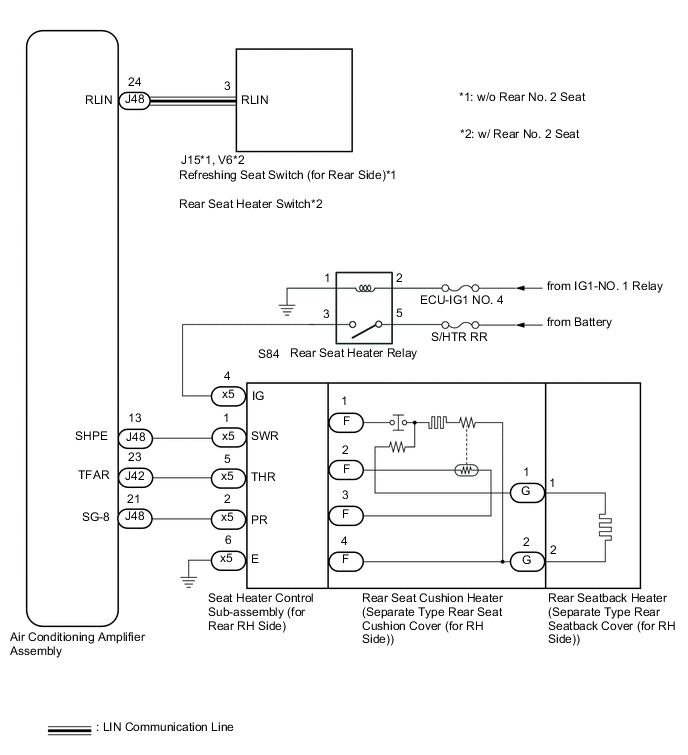
When the refreshing seat switch (for rear side)*1 or rear seat heater switch*2 is operated, the air conditioning amplifier assembly receives the signal and operates the seat heater for the corresponding rear seat.
-
*1: w/o Rear No. 2 Seat
-
*2: w/ Rear No. 2 Seat
WIRING DIAGRAM
CAUTION / NOTICE / HINT
Note
-
If the battery voltage is low, the seat heater system may not operate. If "Operation of Electrical Items Restricted." is displayed on the multi-information display in the combination meter assembly, inspect the battery, referring to On-vehicle Inspection of Charging System.
-
If the battery voltage is low, the seat heater system may not operate. If "Operation of Electrical Items Restricted." is not displayed on the multi-information display in the combination meter assembly, check the Data List item "Battery Control Count (Body ECU)".
-
Inspect the fuses for circuits related to this system before performing the following procedure.
PROCEDURE
-
CLEAR DTC
-
Clear the DTCs.
Body Electrical > Air Conditioner > Clear DTCsResult Proceed to NEXT
NEXT 
-
-
CHECK FOR DTC
-
Check for DTCs.
Body Electrical > Air Conditioner > Trouble CodesOK DTC B14B3 or B14C2 is not output. Result Proceed to OK NG
NG 
GO TO DIAGNOSTIC TROUBLE CODE CHART Click here
OK
-
-
CHECK HARNESS AND CONNECTOR (IG POWER SUPPLY - SEAT HEATER CONTROL SUB-ASSEMBLY (FOR REAR RH SIDE) - BODY GROUND)
-
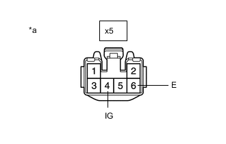
*a Front view of wire harness connector
(to Seat Heater Control Sub-assembly (for Rear RH Side))
Disconnect the x5 seat heater control sub-assembly (for rear RH side) connector.
-
Measure the voltage and resistance according to the value(s) in the table below.
Standard Voltage Tester Connection Condition Specified Condition x5-4 (IG) - Body ground Engine switch on (IG) 11 to 14 V x5-4 (IG) - Body ground Engine switch off Below 1 V Standard Resistance Tester Connection Condition Specified Condition x5-6 (E) - Body ground Always Below 1 Ω Result Proceed to OK NG
NG 
INSPECT REAR SEAT HEATER RELAY Click here
OK
-
-
INSPECT REAR SEAT CUSHION HEATER (SEPARATE TYPE REAR SEAT CUSHION COVER (FOR RH SIDE))
-
Remove the rear seat cushion heater (separate type rear seat cushion cover (for RH side)).
-
Inspect the rear seat cushion heater (separate type rear seat cushion cover (for RH side)).
Result Proceed to OK NG
NG
REPLACE REAR SEAT CUSHION HEATER (SEPARATE TYPE REAR SEAT CUSHION COVER (FOR RH SIDE)) Click here
OK
-
-
INSPECT REAR SEATBACK HEATER (SEPARATE TYPE REAR SEATBACK COVER (FOR RH SIDE))
-
Remove the rear seatback heater (separate type rear seatback cover (for RH side)).
-
Inspect the rear seatback heater (separate type rear seatback cover (for RH side)).
Result Proceed to OK NG
NG
REPLACE REAR SEATBACK HEATER (SEPARATE TYPE REAR SEATBACK COVER (FOR RH SIDE)) Click here
OK
-
-
CHECK HARNESS AND CONNECTOR (AIR CONDITIONING AMPLIFIER ASSEMBLY - SEAT HEATER CONTROL SUB-ASSEMBLY (FOR REAR RH SIDE))
-
Disconnect the J42 and J48 air conditioning amplifier assembly connectors.
-
Measure the resistance according to the value(s) in the table below.
Standard Resistance Tester Connection Condition Specified Condition J48-13 (SHPE) - x5-1 (SWR) Always Below 1 Ω J48-13 (SHPE) or x5-1 (SWR) - Body ground Always 10 kΩ or higher J42-23 (TFAR) - x5-5 (THR) Always Below 1 Ω J42-23 (TFAR) or x5-5 (THR) - Body ground Always 10 kΩ or higher J48-21 (SG-8) - X5-2 (PR) Always Below 1 Ω J48-21 (SG-8) or X5-2 (PR) - Body ground Always 10 kΩ or higher Result Proceed to OK NG
NG
REPAIR OR REPLACE HARNESS OR CONNECTOR
OK
-
-
REPLACE SEAT HEATER CONTROL SUB-ASSEMBLY (FOR REAR RH SIDE)
-
Temporarily replace the seat heater control sub-assembly (for rear RH side) with a new or known good one.
Result Proceed to NEXT
NEXT
-
-
CHECK SEAT HEATER OPERATION
-
Check the operation of the rear seat heater.
OK The seat heater operates normally. Result Result Proceed to OK A NG (w/o Rear No. 2 Seat) B NG (w/ Rear No. 2 Seat) C
A
END (SEAT HEATER CONTROL SUB-ASSEMBLY (FOR REAR RH SIDE) WAS DEFECTIVE)
C
REPLACE REAR SEAT HEATER SWITCH Click here
B
-
-
REPLACE REFRESHING SEAT SWITCH (FOR REAR SIDE)
-
Temporarily replace the refreshing seat switch (for rear side) with a new or known good one.
Result Proceed to NEXT
NEXT
-
-
CHECK SEAT HEATER OPERATION
-
Check the operation of the rear seat heater.
OK The seat heater operates normally. Result Proceed to OK NG
OK
END (REFRESHING SEAT SWITCH (FOR REAR SIDE) WAS DEFECTIVE)
NG
REPLACE AIR CONDITIONING AMPLIFIER ASSEMBLY Click here
-
-
REPLACE REAR SEAT HEATER SWITCH
-
Temporarily replace the rear seat heater switch with a new or known good one.
Result Proceed to NEXT
NEXT
-
-
CHECK SEAT HEATER OPERATION
-
Check the operation of the rear seat heater.
OK The seat heater operates normally. Result Proceed to OK NG
OK
END (REAR SEAT HEATER SWITCH WAS DEFECTIVE)
NG
REPLACE AIR CONDITIONING AMPLIFIER ASSEMBLY Click here
-
-
INSPECT REAR SEAT HEATER RELAY
-
Inspect the rear seat heater relay.
Result Proceed to OK NG
NG
REPLACE REAR SEAT HEATER RELAY
OK
-
-
CHECK HARNESS AND CONNECTOR (IG POWER SUPPLY - REAR SEAT HEATER RELAY)
-
Measure the voltage according to the value(s) in the table below.
Standard Voltage Tester Connection Condition Specified Condition S84-2 - Body ground Engine switch on (IG) 11 V to 14 V S84-5 - Body ground Always 11 V to 14 V Result Proceed to OK NG
NG
REPAIR OR REPLACE HARNESS OR CONNECTOR
OK
-
-
CHECK HARNESS AND CONNECTOR (REAR SEAT HEATER RELAY - SEAT HEATER CONTROL SUB-ASSEMBLY (FOR REAR RH SIDE))
-
Disconnect the x5 seat heater control sub-assembly (for rear RH side) connector.
-
Measure the resistance according to the value(s) in the table below.
Standard Resistance Tester Connection Condition Specified Condition S84-3 - x5-4 (IG) Always Below 1 Ω S84-3 or x5-4 (IG) - Body ground Always 10 kΩ or higher Result Proceed to OK NG
NG
REPAIR OR REPLACE HARNESS OR CONNECTOR
OK
-
-
CHECK HARNESS AND CONNECTOR (REAR SEAT HEATER RELAY - BODY GROUND)
-
Measure the resistance according to the value(s) in the table below.
Standard Resistance Tester Connection Condition Specified Condition S84-1 - Body ground Always Below 1 Ω Result Proceed to OK NG
OK
USE SIMULATION METHOD TO CHECK Click here
NG
REPAIR OR REPLACE HARNESS OR CONNECTOR
-