FRONT POWER SEAT CONTROL SYSTEM(w/ Memory), Diagnostic DTC:B2658
| DTC Code | DTC Name |
|---|---|
| B2658 | Short in Sensor with Motor Power Supply Circuit |
DESCRIPTION
This DTC is stored when the slide motor is being operated (the slide motor position sensor is being supplied with power) and the power supply voltage does not rise to the specified value.
| DTC No. | Detection Item | DTC Detection Condition | Trouble Area |
|---|---|---|---|
| B2658 | Short in Sensor with Motor Power Supply Circuit | Slide motor position sensor power supply voltage is low |
|
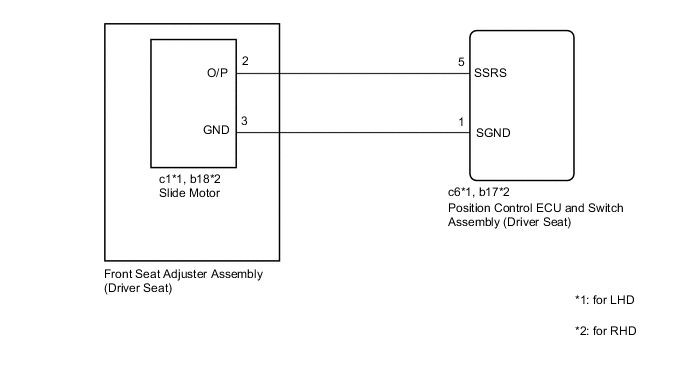
WIRING DIAGRAM
PROCEDURE
-
CLEAR DTC
-
Clear the DTCs.
Body Electrical > Driver Seat > Clear DTCsResult Proceed to NEXT
NEXT 
-
-
CHECK FOR DTC
-
Check for DTCs.
Body Electrical > Driver Seat > Trouble CodesOK DTC B2658 is not output. Result Proceed to OK NG
OK 
USE SIMULATION METHOD TO CHECK Click here
NG
-
-
CHECK HARNESS AND CONNECTOR (POSITION CONTROL ECU AND SWITCH ASSEMBLY (DRIVER SEAT) - SLIDE MOTOR (FRONT SEAT ADJUSTER ASSEMBLY (DRIVER SEAT)))
-
Disconnect the c6*1 or b17*2 position control ECU and switch assembly (driver seat) connector.
-
Disconnect the c1*1 or b18*2 slide motor (front seat adjuster assembly (driver seat)) connector.
-
*1: for LHD
-
*2: for RHD
-
-
Measure the resistance according to the value(s) in the table below.
Standard Resistance for LHD Tester Connection Condition Specified Condition c6-5 (SSRS) - c1-2 Always Below 1 Ω c6-5 (SSRS) or c1-2 - Body ground Always 10 kΩ or higher c6-1 (SGND) - c1-3 Always Below 1 Ω c6-1 (SGND) or c1-3 - Body ground Always 10 kΩ or higher for RHD Tester Connection Condition Specified Condition b17-5 (SSRS) - b18-2 Always Below 1 Ω b17-5 (SSRS) or b18-2 - Body ground Always 10 kΩ or higher b17-1 (SGND) - b18-3 Always Below 1 Ω b17-1 (SGND) or b18-3 - Body ground Always 10 kΩ or higher Result Proceed to OK NG
NG
REPAIR OR REPLACE HARNESS OR CONNECTOR
OK
-
-
CHECK POSITION CONTROL ECU AND SWITCH ASSEMBLY (DRIVER SEAT) (SLIDE MOTOR CIRCUIT)
-
Reconnect the c1*1 or b18*2 slide motor (front seat adjuster assembly (driver seat)) connector.
-
*1: for LHD
-
*2: for RHD
-
-
Measure the voltage according to the value(s) in the table below.
Standard Voltage for LHD Tester Connection Condition Specified Condition c1-2 - c1-3 Slide switch on 4.8 to 5.1 V for RHD Tester Connection Condition Specified Condition b18-2 - b18-3 Slide switch on 4.8 to 5.1 V Result Proceed to OK NG
OK
REPLACE FRONT SEAT ADJUSTER ASSEMBLY (DRIVER SEAT) Click here
NG
REPLACE POSITION CONTROL ECU AND SWITCH ASSEMBLY (DRIVER SEAT) Click here
-