PRE-CRASH SAFETY SYSTEM, Diagnostic DTC:C1A4B
| DTC Code | DTC Name |
|---|---|
| C1A4B | Stop Light Relay Circuit |
DESCRIPTION
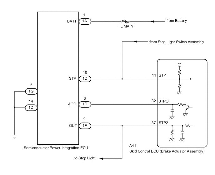
The skid control ECU (brake actuator assembly) sends a stop light operation request signal to the semiconductor power integration ECU (stop light relay). If the skid control ECU (brake actuator assembly) detects a malfunction in the stop light relay circuit, the driving support ECU assembly stores DTC C1A4B.
| DTC No. | Detection Item | DTC Detection Condition | Trouble Area |
|---|---|---|---|
| C1A4B | Stop Light Relay Circuit | Diagnosis condition:
Malfunction condition: Either of the following conditions is met:
|
|
WIRING DIAGRAM
CAUTION / NOTICE / HINT
Note
-
Inspect the fuses for circuits related to this system before performing the following procedure.
-
When this DTC is output, a malfunction in the lighting system is suspected. Check if the lighting system is functioning normally.
-
The pre-crash safety system uses the CAN communication system. First, confirm that there are no malfunction in the CAN communication system. Refer to How to Proceed with Troubleshooting.
PROCEDURE
-
INSPECT ENGINE START
-
Depress the brake pedal, push the engine switch and check that the engine starts.
OK The engine starts. Result Result Proceed to OK A NG (for 8AR-FTS) B NG (for 2GR-FKS) C
B 
GO TO SFI SYSTEM Click here
C
GO TO SFI SYSTEM w/ Canister Pump Module: Click here w/o Canister Pump Module: Click here
A 
-
-
CHECK STOP LIGHT OPERATION
-
Check that the stop lights come on when the brake pedal is depressed and go off when the brake pedal is released.
OK The stop lights illuminate when the brake pedal is depressed. The stop lights turn off when the brake pedal is released. Result Proceed to OK NG
NG
GO TO LIGHTING SYSTEM Click here
OK
-
-
INSPECT SEMICONDUCTOR POWER INTEGRATION ECU
-
Turn the engine switch off.
-
Inspect the semiconductor power integration ECU.
OK The semiconductor power integration ECU is normal. Result Proceed to OK NG
NG 
REPLACE SEMICONDUCTOR POWER INTEGRATION ECU Click here
OK
-
-
CHECK HARNESS AND CONNECTOR (STPO TERMINAL VOLTAGE)
-
Turn the engine switch off.
-
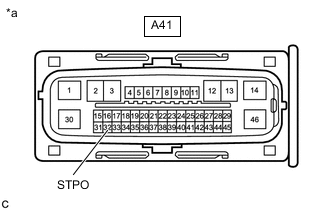
*a Front view of wire harness connector
(to Skid control ECU (brake actuator assembly))
Disconnect the A41 skid control ECU (brake actuator assembly) connector.
-
Measure the voltage according to the value(s) in the table below.
Standard Voltage Tester Connection Condition Specified Condition A41-32 (STPO) - Body ground Always 11 to 14 V -
Connect the A41 skid control ECU (brake actuator assembly) connector.
Result Proceed to OK NG
NG
CHECK HARNESS AND CONNECTOR (SEMICONDUCTOR POWER INTEGRATION ECU - SKID CONTROL ECU) Click here
OK
-
-
PERFORM ACTIVE TEST USING GTS (STOP LIGHT RELAY OUTPUT)
-
According to the display on the GTS, perform the Active Test Stop Light Relay.
Chassis > ABS/VSC/TRC/EPB > Active TestTester Display Measurement Item Control Range Diagnostic Note Stop Light Relay Stop lights ON / OFF Test possible at vehicle speed of 0 km/h (0 mph)
Chassis > ABS/VSC/TRC/EPB > Active TestActive Test Display Stop Light Relay Data List Display Stop Light Relay Output -
According to the display on the GTS, read the Data List item Stop Light Relay.
Chassis > ABS/VSC/TRC/EPB > Data ListTester Display Measurement Item Range Normal Condition Diagnostic Note Stop Light Relay Output STPO terminal output condition ON or OFF ON: Output
OFF: Not output
- -
Check that the Data List item Stop Light Relay Output changes between ON and OFF and the stop lights turn on and off according to the operation of the Active Test.
Result Result Proceed to The Data List item Stop Light Relay Output does not change between ON and OFF and the stop lights do not turn ON and OFF according to the operation of the Active Test. A The Data List item Stop Light Relay Output changes between ON and OFF but the stop lights do not turn ON and OFF according to the operation of the Active Test. B
B
CHECK HARNESS AND CONNECTOR (SEMICONDUCTOR POWER INTEGRATION ECU - SKID CONTROL ECU) Click here
A
-
-
INSPECT SKID CONTROL ECU (BRAKE ACTUATOR ASSEMBLY)
-
According to the display on the GTS, perform the Active Test Stop Light Relay.
Chassis > ABS/VSC/TRC/EPB > Active TestTester Display Measurement Item Control Range Diagnostic Note Stop Light Relay Stop lights ON / OFF Test possible at vehicle speed of 0 km/h (0 mph)
Chassis > ABS/VSC/TRC/EPB > Active TestTester Display Stop Light Relay -
Measure the voltage according to the value(s) in the table below.
Tech Tips
Do not disconnect the semiconductor power integration ECU connector.
Standard Voltage Tester Connection Condition Specified Condition 1D-3 (ACC) - Body ground Engine switch on (IG)
(Active test OFF)
11 to 14 V Engine switch on (IG)
(Active test ON)
Below 1.5 V Result Proceed to OK NG
NG
REPLACE SKID CONTROL ECU (BRAKE ACTUATOR ASSEMBLY) Click here
OK
-
-
REPLACE SEMICONDUCTOR POWER INTEGRATION ECU
-
Replace the semiconductor power integration ECU.
Result Proceed to NEXT
NEXT
-
-
CHECK DTC OUTPUT (VEHICLE STABILITY CONTROL SYSTEM)
-
Clear the DTCs.
Chassis > ABS/VSC/TRC/EPB > Clear DTCs -
According to the display on the GTS, perform the Active Test Stop Light Relay.
Chassis > ABS/VSC/TRC/EPB > Active TestTester Display Measurement Item Control Range Diagnostic Note Stop Light Relay Stop lights ON / OFF Test possible at vehicle speed of 0 km/h (0 mph)
Chassis > ABS/VSC/TRC/EPB > Active TestTester Display Stop Light Relay -
Check for DTCs.
Chassis > ABS/VSC/TRC/EPB > Trouble CodesResult Result Proceed to DTC C1380 is not output A DTC C1380 is output B
A
END
B
GO TO DTC CHART (C1380) Click here
-
-
REPLACE SEMICONDUCTOR POWER INTEGRATION ECU
-
Replace the semiconductor power integration ECU.
Result Proceed to NEXT
NEXT
GO TO STEP 8 Click here
-
-
REPLACE SKID CONTROL ECU (BRAKE ACTUATOR ASSEMBLY)
-
Replace the skid control ECU (brake actuator assembly).
Result Proceed to NEXT
NEXT
GO TO STEP 8 Click here
-
-
CHECK HARNESS AND CONNECTOR (SEMICONDUCTOR POWER INTEGRATION ECU - SKID CONTROL ECU)
-
Turn the engine switch off.
-
Remove the semiconductor power integration ECU.
-
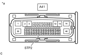
*a Front view of wire harness connector
(to Skid control ECU (brake actuator assembly))
Disconnect the A41 skid control ECU (brake actuator assembly) connector.
-
Measure the resistance according to the value(s) in the table below.
Standard Resistance Tester Connection Condition Specified Condition 1F-9 (OUT) - A41-37 (STP2) Always Below 1 Ω -
Connect the A41 skid control ECU (brake actuator assembly) connector.
-
Install the semiconductor power integration ECU.
Result Proceed to OK NG
NG
REPAIR OR REPLACE HARNESS OR CONNECTOR Click here
OK
-
-
REPLACE SKID CONTROL ECU (BRAKE ACTUATOR ASSEMBLY)
-
Replace the skid control ECU (brake actuator assembly).
Result Proceed to NEXT
NEXT
GO TO STEP 8 Click here
-
-
REPAIR OR REPLACE HARNESS OR CONNECTOR
-
Repair or replace the harness or connector.
Result Proceed to NEXT
NEXT
GO TO STEP 8 Click here
-
-
CHECK HARNESS AND CONNECTOR (SEMICONDUCTOR POWER INTEGRATION ECU - SKID CONTROL ECU)
-
Turn the engine switch off.
-
Remove the semiconductor power integration ECU.
-
Disconnect the A41 skid control ECU (brake actuator assembly) connector.
-
Measure the resistance according to the value(s) in the table below.
Standard Resistance Tester Connection Condition Specified Condition 1D-3 (ACC) - A41-32 (STPO) Always Below 1 Ω 1D-3 (ACC) or A41-32 (STPO) - Body ground Always 10 kΩ or higher -
Connect the A41 skid control ECU (brake actuator assembly) connector.
-
Install the semiconductor power integration ECU.
Result Proceed to OK NG
NG
REPAIR OR REPLACE HARNESS OR CONNECTOR Click here
OK
-
-
REPLACE SEMICONDUCTOR POWER INTEGRATION ECU
-
Replace the semiconductor power integration ECU.
Result Proceed to NEXT
NEXT
GO TO STEP 8 Click here
-
-
REPAIR OR REPLACE HARNESS OR CONNECTOR
-
Repair or replace the harness or connector.
Result Proceed to NEXT
NEXT
GO TO STEP 8 Click here
-