COMBINATION METER INSTALLATION
PROCEDURE
-
INSTALL COMBINATION METER ASSEMBLY
-
Connect each connector.
-
Engage the clamp.
-
Install the combination meter assembly with the 4 screws.
-
-
INSTALL INSTRUMENT CLUSTER FINISH PANEL SUB-ASSEMBLY
-
Connect the connector.
-
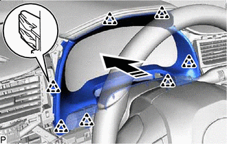

Install in this Direction Engage the 7 clips as shown in the illustration.
-
Engage the 4 clips and 2 claws to install the instrument cluster finish panel sub-assembly.
-
-
INSTALL LOWER INSTRUMENT FINISH PANEL SUB
-
INSTALL INSTRUMENT CLUSTER FINISH PANEL ORNAMENT
-
INSTALL LOWER NO. 1 INSTRUMENT PANEL FINISH PANEL
-
INSTALL LOWER NO. 2 INSTRUMENT PANEL FINISH PANEL
-
INSTALL LOWER INSTRUMENT PANEL FINISH PANEL SUB-ASSEMBLY
-
CONNECT HOOD LOCK CONTROL LEVER SUB-ASSEMBLY
-
INSTALL NO. 1 INSTRUMENT PANEL UNDER COVER SUB-ASSEMBLY
-
INSTALL COWL SIDE TRIM BOARD
-
INSTALL FRONT DOOR SCUFF PLATE
-
INSTALL INSTRUMENT PANEL GARNISH
-
CONNECT CABLE TO NEGATIVE BATTERY TERMINAL
Note
When disconnecting the cable, some systems need to be initialized after the cable is reconnected.
-
CUSTOMIZE POWER TILT AND POWER TELESCOPIC STEERING COLUMN SYSTEM