LIGHTING SYSTEM Instrument Panel Box Light and Footwell Light Circuit
DESCRIPTION
The main body ECU (multiplex network body ECU) detects the condition of the rear door courtesy light switch assembly.
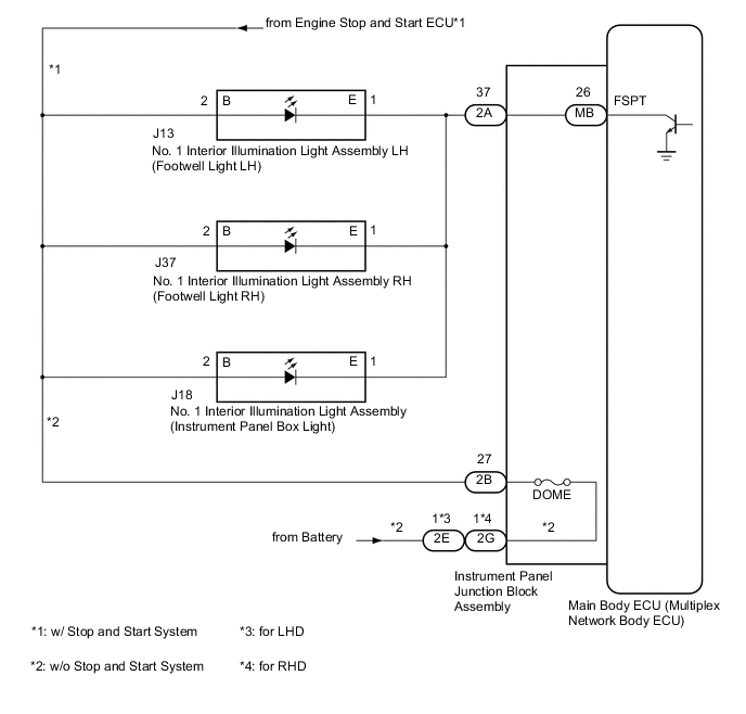
WIRING DIAGRAM
CAUTION / NOTICE / HINT
Note
-
Before replacing the main ECU (multiplex network body ECU), refer to Service Bulletin.
-
The vehicle battery supplies power to the main body ECU (multiplex network body ECU) via the door control battery. Therefore, before proceeding with troubleshooting, perform an on-vehicle inspection and confirm that the main body ECU (multiplex network body ECU) power source circuit is normal.*
-
*: w/o Canister Pump Module with Door Ajar Warning Buzzer Function
PROCEDURE
-
PERFORM ACTIVE TEST USING GTS
-
Connect the GTS to the DLC3.
-
Start the engine.
-
Turn the GTS on.
-
Enter the following menus: Body Electrical / (desired system) / Active Test.
-
Perform the Active Test according to the display on the GTS.
Body Electrical > Main Body > Active TestTester Display Measurement Item Control Range Diagnostic Note Fr Foot Light Footwell light and instrument panel box light ON or OFF -
Body Electrical > Main Body > Active TestTester Display Fr Foot Light OK Footwell light and instrument panel box lights comes on. Result Result Proceed to OK A NG (w/o Stop and start system) B NG (w/ Stop and start system) C
A 
PROCEED TO NEXT SUSPECTED AREA SHOWN IN PROBLEM SYMPTOMS TABLE Click here
C 
CHECK HARNESS AND CONNECTOR (ENGINE STOP AND START ECU - No. 1 INTERIOR ILLUMINATION LIGHT ASSEMBLY) Click here
B 
-
-
CHECK HARNESS AND CONNECTOR (POWER SOURCE - INSTRUMENT PANEL JUNCTION BLOCK ASSEMBLY)
-
Disconnect the 2E*1 or 2G*2 instrument panel junction block assembly connector.
-
Measure the voltage according to the value(s) in the table below.
Standard Voltage Tester Connection Condition Specified Condition 2E-1 - Body ground*1 Always 11 to 14 V 2G-1 - Body ground*2 Always 11 to 14 V
-
*1: for LHD
-
*2: for RHD
Result Proceed to OK NG -
NG
REPAIR OR REPLACE HARNESS OR CONNECTOR
OK
-
-
INSPECT INSTRUMENT PANEL JUNCTION BLOCK ASSEMBLY
-
Disconnect the 2B instrument panel junction block assembly connector.
-
Measure the resistance according to the value(s) in the table below.
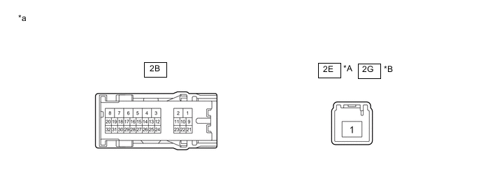
*A for LHD *B for RHD *a Component without harness connected
(Instrument Panel Junction Block Assembly)
- - Standard Resistance Tester Connection Condition Specified Condition 2E-1*1 - 2B-27 Always Below 1 Ω 2G-1*2 - 2B-27 Always Below 1 Ω
-
*1: for LHD
-
*2: for RHD
Result Proceed to OK NG -
NG
REPLACE INSTRUMENT PANEL JUNCTION BLOCK ASSEMBLY Click here
OK
-
-
CHECK HARNESS AND CONNECTOR (No. 1 INTERIOR ILLUMINATION LIGHT ASSEMBLY - INSTRUMENT PANEL JUNCTION BLOCK ASSEMBLY)
-
Disconnect the J13 No. 1 interior illumination light assembly LH connector.
-
Disconnect the J37 No. 1 interior illumination light assembly RH connector.
-
Disconnect the J18 No. 1 interior illumination light assembly connector.
-
Measure the resistance according to the value(s) in the table below.
Standard Resistance Tester Connection Condition Specified Condition 2B-27 - J13-2(B) Always Below 1 Ω 2B-27 - J37-2(B) Always Below 1 Ω 2B-27 - J18-2(B) Always Below 1 Ω J13-2(B) or 2B-27 - Body ground Always 10 kΩ or higher J37-2(B) or 2B-27 - Body ground Always 10 kΩ or higher J18-2(B) or 2B-27 - Body ground Always 10 kΩ or higher Result Proceed to OK NG
NG
REPAIR OR REPLACE HARNESS OR CONNECTOR
OK
-
-
CHECK HARNESS AND CONNECTOR (No. 1 INTERIOR ILLUMINATION LIGHT ASSEMBLY - INSTRUMENT PANEL JUNCTION BLOCK ASSEMBLY)
-
Disconnect the 2A instrument panel junction block assembly connector.
-
Measure the resistance according to the value(s) in the table below.
Standard Resistance Tester Connection Condition Specified Condition 2A-37 - J13-1(E) Always Below 1 Ω 2A-37 - J37-1(E) Always Below 1 Ω 2A-37 - J18-1(E) Always Below 1 Ω J13-1(E) or 2A-37 - Body ground Always 10 kΩ or higher J37-1(E) or 2A-37 - Body ground Always 10 kΩ or higher J18-1(E) or 2A-37 - Body ground Always 10 kΩ or higher Result Proceed to OK NG
NG
REPAIR OR REPLACE HARNESS OR CONNECTOR
OK
-
-
INSPECT INSTRUMENT PANEL JUNCTION BLOCK ASSEMBLY
-
Remove the instrument panel junction block assembly.
-
Remove the main body ECU (multiplex network body ECU) from the instrument panel junction block assembly.
-
Measure the resistance according to the value(s) in the table below.
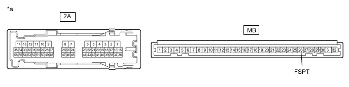
*a Component without harness connected
(Instrument Panel Junction Block Assembly)
- - Standard Resistance Tester Connection Condition Specified Condition 2A-37 - MB-26 (FSPT) Always Below 1 Ω Result Proceed to OK NG
OK
REPLACE MAIN BODY ECU (MULTIPLEX NETWORK BODY ECU) Click here
NG
REPLACE INSTRUMENT PANEL JUNCTION BLOCK ASSEMBLY Click here
-
-
CHECK HARNESS AND CONNECTOR (ENGINE STOP AND START ECU - No. 1 INTERIOR ILLUMINATION LIGHT ASSEMBLY)
-
Disconnect the J13 No. 1 interior illumination light assembly LH connector.
-
Disconnect the J37 No. 1 interior illumination light assembly RH connector.
-
Disconnect the J18 No. 1 interior illumination light assembly connector.
-
Measure the voltage according to the value(s) in the table below.
Standard Voltage Tester Connection Condition Specified Condition J13-2 - Body ground Always 10.5 to 16 V J37-2 - Body ground Always 10.5 to 16 V J18-2 - Body ground Always 10.5 to 16 V Result Proceed to OK NG
NG
GO TO STOP AND START SYSTEM Click here
OK
-
-
CHECK HARNESS AND CONNECTOR (No. 1 INTERIOR ILLUMINATION LIGHT ASSEMBLY - INSTRUMENT PANEL JUNCTION BLOCK ASSEMBLY)
-
Measure the resistance according to the value(s) in the table below.
Standard Resistance Tester Connection Condition Specified Condition 2A-37 - J13-1(E) Always Below 1 Ω 2A-37 - J37-1(E) Always Below 1 Ω 2A-37 - J18-1(E) Always Below 1 Ω J13-1(E) or 2A-37 - Body ground Always 10 kΩ or higher J37-1(E) or 2A-37 - Body ground Always 10 kΩ or higher J18-1(E) or 2A-37 - Body ground Always 10 kΩ or higher Result Proceed to OK NG
OK
GO TO STEP 6 Click here
NG
REPAIR OR REPLACE HARNESS OR CONNECTOR
-