LIGHTING SYSTEM Back Door Courtesy Switch Circuit
DESCRIPTION
-
The main body ECU (multiplex network body ECU) detects the condition of the back door courtesy switch built into the back door lock assembly.*1
-
The multiplex network door ECU receives the courtesy light switch signal from the back door lock assembly and transmits it to the main body ECU (multiplex network body ECU) via CAN communication.*2
*1: w/o Power Back Door System
*2: w/ Power Back Door System
WIRING DIAGRAM
-
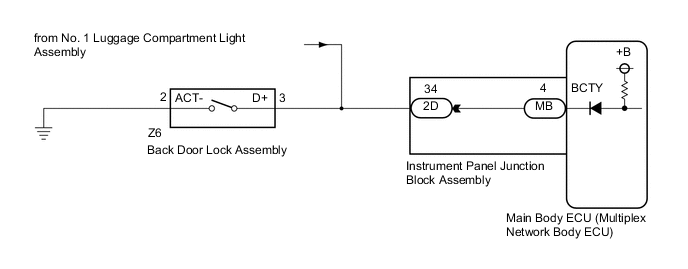
w/ Power Back Door System
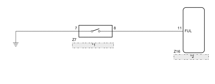
*1 Back Door Lock Assembly *2 Multiplex Network Door ECU -
w/o Power Back Door System
CAUTION / NOTICE / HINT
Note
-
Before replacing the main body ECU (multiplex network body ECU), refer to Service Bulletin.
-
The vehicle battery supplies power to the main body ECU (multiplex network body ECU) via the door control battery. Therefore, before proceeding with troubleshooting, perform an on-vehicle inspection and confirm that the main body ECU (multiplex network body ECU) power source circuit is normal.*
-
*: w/o Canister Pump Module with Door Ajar Warning Buzzer Function
PROCEDURE
-
READ VALUE USING GTS
-
Connect the GTS to the DLC3.
-
Turn the ignition switch to ON.
-
Turn the GTS on.
-
Enter the following menus: Body Electrical / Main Body / Data List.
-
Read the Data List according to the display on the GTS.
Body Electrical > Main Body > Data ListTester Display Measurement Item Range Normal Condition Diagnostic Note Back Door Courtesy SW Back door courtesy switch signal ON or OFF ON: Back door open
OFF: Back door closed
-
Body Electrical > Main Body > Data ListTester Display Back Door Courtesy SW OK Normal conditions listed above are displayed. Result Result Proceed to OK A NG (w/ Power back door system) B NG (w/o Power back door system) C
A 
PROCEED TO NEXT SUSPECTED AREA SHOWN IN PROBLEM SYMPTOMS TABLE Click here
C 
INSPECT BACK DOOR LOCK ASSEMBLY Click here
B 
-
-
INSPECT BACK DOOR LOCK ASSEMBLY
-
Remove the back door lock assembly.
-
Inspect the back door courtesy switch built in the back door lock assembly.
OK Back door lock assembly is normal. Result Proceed to OK NG
NG
REPLACE BACK DOOR LOCK ASSEMBLY Click here
OK
-
-
CHECK HARNESS AND CONNECTOR (BACK DOOR LOCK ASSEMBLY - MULTIPLEX NETWORK DOOR ECU AND BODY GROUND OR BODY GROUND)
-
Disconnect the Z16 multiplex network door ECU connector.
-
Measure the resistance according to the value(s) in the table below.
Standard Resistance Tester Connection Condition Specified Condition Z7-8 - Z16-11 (FUL) Always Below 1 Ω Z7-8 or Z16-11 (FUL) - Body ground Always 10 kΩ or higher Z7-7 - Body ground Always Below 1 Ω Result Proceed to OK NG
OK
REPLACE MULTIPLEX NETWORK DOOR ECU Click here
NG
REPAIR OR REPLACE HARNESS OR CONNECTOR
-
-
INSPECT BACK DOOR LOCK ASSEMBLY
-
Remove the back door lock assembly.
-
Inspect the back door courtesy switch built in the back door lock assembly.
OK Back door lock assembly is normal. Result Proceed to OK NG
NG
REPLACE BACK DOOR LOCK ASSEMBLY Click here
OK
-
-
CHECK HARNESS AND CONNECTOR (BACK DOOR LOCK ASSEMBLY - INSTRUMENT PANEL JUNCTION BLOCK ASSEMBLY OR BODY GROUND)
-
Disconnect the 2D instrument panel junction block assembly connector.
-
Measure the resistance according to the value(s) in the table below.
Standard Resistance Tester Connection Condition Specified Condition Z6-3 (D+) - 2D-34 Always Below 1 Ω Z6-3 (D+) or 2D-34 - Body ground Always 10 kΩ or higher Z6-2 (ACT-) - Body ground Always Below 1 Ω Result Proceed to OK NG
NG
REPAIR OR REPLACE HARNESS OR CONNECTOR
OK
-
-
INSPECT INSTRUMENT PANEL JUNCTION BLOCK ASSEMBLY
-
Remove the instrument panel junction block assembly.
-
Remove the main body ECU (multiplex network body ECU) from the instrument panel junction block assembly.
-
Measure the resistance according to the value(s) in the table below.
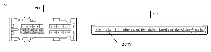
*a Component without harness connected
(Instrument Panel Junction Block Assembly)
- - Standard Resistance Tester Connection Condition Specified Condition MB-4 (BCTY) - 2D-34 Always Below 1 Ω Result Proceed to OK NG
OK
REPLACE MAIN BODY ECU (MULTIPLEX NETWORK BODY ECU) Click here
NG
REPLACE INSTRUMENT PANEL JUNCTION BLOCK ASSEMBLY Click here
-