LIGHTING SYSTEM TERMINALS OF ECU
-
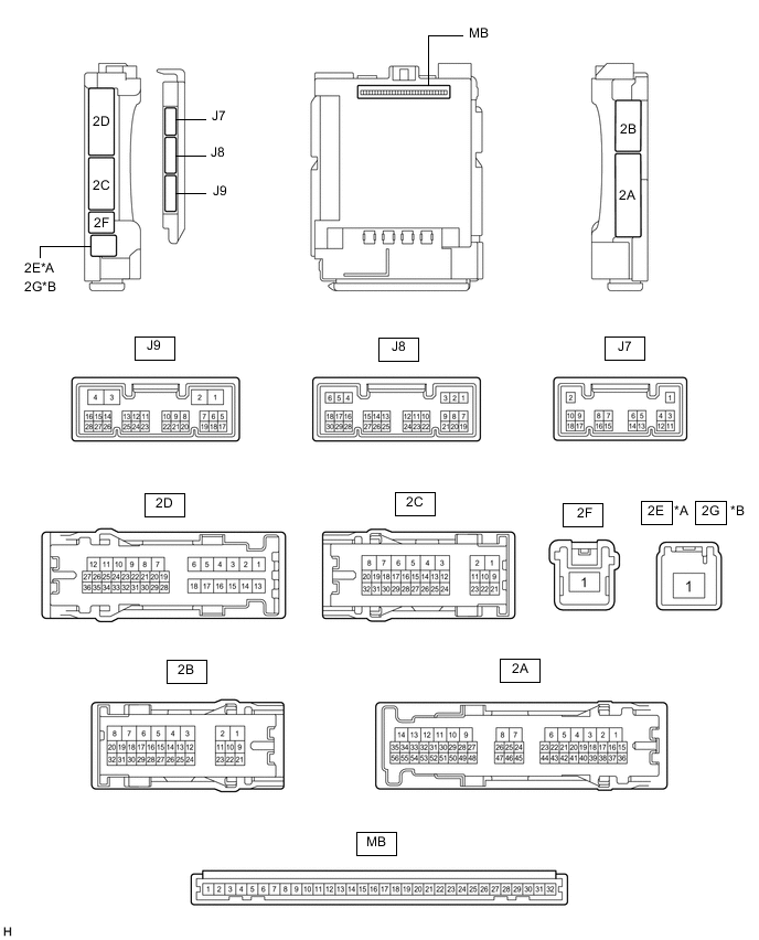
CHECK INSTRUMENT PANEL JUNCTION BLOCK ASSEMBLY AND MAIN BODY ECU (MULTIPLEX NETWORK BODY ECU)
*A for LHD *B for RHD
-
Disconnect the instrument panel junction block assembly and main body ECU (multiplex network body ECU) connectors.
-
Measure the voltage on the wire harness side connector according to the value(s) in the table below.
Terminal No. Wiring Color Terminal Description Condition Specified Condition 2B-23 - Body ground*4 GR - Body ground Battery power supply Always 11 to 14 V 2C-1 - Body ground*3 W - Body ground Battery power supply Always 11 to 14 V 2E-1 - Body ground*1 B - Body ground Battery power supply Always 11 to 14 V 2G-1 - Body ground*2 B - Body ground Battery power supply Always 11 to 14 V If the result is not as specified, there may be a malfunction in the wire harness.
*1: for LHD
*2: for RHD
*3: w/ Door control battery
*4: w/o Door control battery
-
Measure the resistance on the wire harness side connector according to the value(s) in the table below.
Terminal No. (Symbol) Wiring Color Terminal Description Condition Specified Condition 2B-3 - Body ground W-B - Body ground Ground Always Below 1 Ω 2A-19 - Body ground* W-B - Body ground Ground Always Below 1 Ω If the result is not as specified, there may be a malfunction in the wire harness.
*: w/ Stop and start system
-
Reconnect the instrument panel junction block assembly and main body ECU (multiplex network body ECU) connectors.
-
Measure the voltage and check for pulses according to the value(s) in the table below.
Terminal No. (Symbol) Wiring Color Terminal Description Condition Specified Condition 2A-30 - Body ground GR - Body ground ACC power supply Engine switch on (ACC) 11 to 14 V Engine switch off Below 1 V 2A-17 - Body ground G - Body ground IG power supply Engine switch on (IG) 11 to 14 V Engine switch off Below 1 V 2B-26 - Body ground P - Body ground Scuff light power supply Always 11 to 14 V 2B-27 - Body ground LA-G - Body ground Footwell light, instrument panel box light and instrument panel ambient illumination light power supply Always 11 to 14 V 2B-25 - Body ground*2 Y - Body ground Door ambient illumination light LH power supply Always 11 to 14 V 2B-24 - Body ground*2 L - Body ground Door ambient illumination light RH power supply Always 11 to 14 V 2D-19 - Body ground B - Body ground No. 1 luggage compartment light power supply DOME CUT relay on 11 to 14 V DOME CUT relay off Below 1 V 2B-9 - Body ground L - Body ground Courtesy light LH power supply DOME CUT relay on 11 to 14 V DOME CUT relay off Below 1 V 2B-10 - Body ground W - Body ground Map light assembly, courtesy light RH and vanity lights power supply DOME CUT relay on 11 to 14 V DOME CUT relay off Below 1 V 2A-16 - Body ground*3 B - Body ground DOME CUT No. 2 relay power supply DOME CUT relay on 11 to 14 V DOME CUT relay off Below 1 V 2C-7 - Body ground*3 W - Body ground Power supply Engine switch on (IG) 10.5 to 16 V 2B-5 - Body ground*3 SB - Body ground Spot light assembly power supply DOME CUT No. 2 relay on 10.5 to 16 V DOME CUT No. 2 relay off Below 1 V 2B-29 - Body ground GR - Body ground Interior lights drive output Interior lights off (when operated by illuminated entry system) 11 to 14 V Interior lights on (when operated by illuminated entry system) Below 1 V 2A-37 - Body ground W - Body ground Footwell light and instrument panel box light output Footwell light and instrument panel box light off 10.5 to 16 V*3
11 to 14 V*4
Footwell light and instrument panel box light at full brightness Below 1 V J9-27 (DMDR) - Body ground BE - Body ground Door switch signal input Door switch on Below 1 V Door switch off Pulse generation J9-28 (DMON) - Body ground LG - Body ground Front dome light switch signal input Front dome light switch on Below 1 V Front dome light switch off Pulse generation 2D-24 - Body ground W - Body ground Rear door courtesy light switch LH input Rear door LH open Below 1 V Rear door LH closed 11 to 14 V 2A-31 - Body ground R - Body ground Rear door courtesy light switch RH input Rear door RH open Below 1 V Rear door RH closed 11 to 14 V J8-6 (FLCY) - Body ground P - Body ground Front door courtesy light switch LH input Front door LH open Below 1 V Front door LH closed 11 to 14 V J8-27 (FRCY) - Body ground R - Body ground Front door courtesy light switch RH input Front door RH open Below 1 V Front door RH closed 11 to 14 V 2D-34 - Body ground*5 Y - Body ground Back door courtesy light switch input Back door open Below 1 V Back door closed 11 to 14 V J9-2 (LSWR) - Body ground L - Body ground Rear door unlock detection switch RH input Rear door RH locked Pulse generation Rear door RH unlocked Below 1 V 2B-14 - Body ground V - Body ground Rear door unlock detection switch LH input Rear door LH locked Pulse generation Rear door LH unlocked Below 1 V 2B-13 - Body ground B - Body ground Front door unlock detection switch LH input Front door LH locked Pulse generation Front door LH unlocked Below 1 V 2B-12 - Body ground P - Body ground Front door unlock detection switch RH input Front door RH locked Pulse generation Front door RH unlocked Below 1 V J7-1 (RCYL) - Body ground G - Body ground Rear door courtesy light RH drive output Rear door courtesy light RH off 11 to 14 V Rear door courtesy light RH on Below 1 V J7-2 (LCYL) - Body ground Y - Body ground Rear door courtesy light LH drive output Rear door courtesy light LH off 11 to 14 V Rear door courtesy light LH on Below 1 V J9-17 (FRCL) - Body ground SB - Body ground Front door courtesy light RH drive output Front door courtesy light RH off 11 to 14 V Front door courtesy light RH on Below 1 V J9-1 (FLCL) - Body ground W - Body ground Front door courtesy light LH drive output Front door courtesy light LH off 11 to 14 V Front door courtesy light LH on Below 1 V J9-21 (LED1) - Body ground*1 L - Body ground Instrument panel ambient illumination light output Instrument panel ambient illumination light off 10.5 to 16 V*3
11 to 14 V*4
Instrument panel ambient illumination light dimmer control operating (dimming) Pulse generation Instrument panel ambient illumination light at full brightness Below 2.2 V J9-22 (LED2) - Body ground*2 V - Body ground Door ambient illumination light output Door ambient illumination light off 10.5 to 16 V*3
11 to 14 V*4
Door ambient illumination light dimmer control operating (dimming) Pulse generation Door ambient illumination light at full brightness Below 2.2 V If the result is not as specified, the main body ECU (multiplex network body ECU) or instrument panel junction block assembly may be malfunctioning.
*1: w/ Instrument panel ambient illumination light
*2: w/ Door ambient illumination light
*3: w/ Stop and start system
*4: w/o Stop and start system
*5: w/o Power back door system
-
-
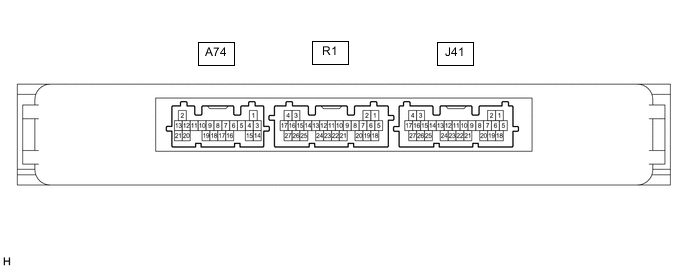
CHECK CERTIFICATION ECU (SMART KEY ECU ASSEMBLY)
-
Measure the voltage according to the value(s) in the table below.
Terminal No. (Symbol) Wiring Color Terminal Description Condition Specified Condition J41-10 (SWIL) - J41-11 (AGND) W - R Engine switch illumination drive output Engine switch illumination on 11 to 14 V Engine switch illumination off Below 1 V
-
If the result is not as specified, the certification ECU (smart key ECU assembly) may be malfunctioning.
-
-
-
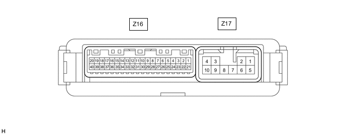
CHECK MULTIPLEX NETWORK DOOR ECU (w/ Power Back Door)
-
Disconnect the Z16 and Y17 multiplex network door ECU connectors.
-
Measure the voltage according to the value(s) in the table below.
Tech Tips
Measure the values on the wire harness side with the connector disconnected.
Terminal No. (Symbol) Wiring Color Terminal Description Condition Specified Condition Z16-20 (ECUB) - Body ground GR - Body ground Battery power supply Always 11 to 14 V Z16-18 (IG) - Body ground P - Body ground IG power supply Engine switch on (IG) 11 to 14 V Engine switch off Below 1 V Z17-1 (B) - Body ground Y - Body ground Battery power supply Always 11 to 14 V
-
If the result is not as specified, the multiplex network door ECU may be malfunctioning.
-
-
Reconnect the Z16 and Z17 multiplex network door ECU connectors.
-
Measure the voltage and check for pulses according to the value(s) in the table below.
Terminal No. (Symbol) Wiring Color Terminal Description Condition Specified Condition Z17-5 (CTYO) - Body ground W - Body ground Luggage compartment light drive output Back door closed (when No. 1 luggage compartment light switch on) 11 to 14 V Back door open (when No. 1 luggage compartment light switch on) Below 1 V Z16-11 (FUL) - Body ground V - Body ground Back door lock assembly (latch courtesy switch) signal circuit Back door closed → open Pulse generation → Below 1 V
-